Servo Tester
$2.75
Simple tester for servo motors or ECS
15 in stock
Description
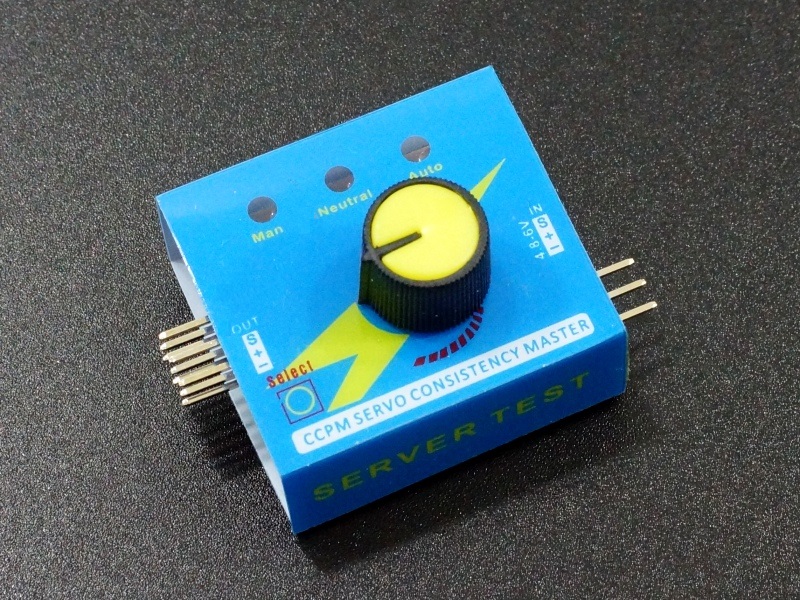
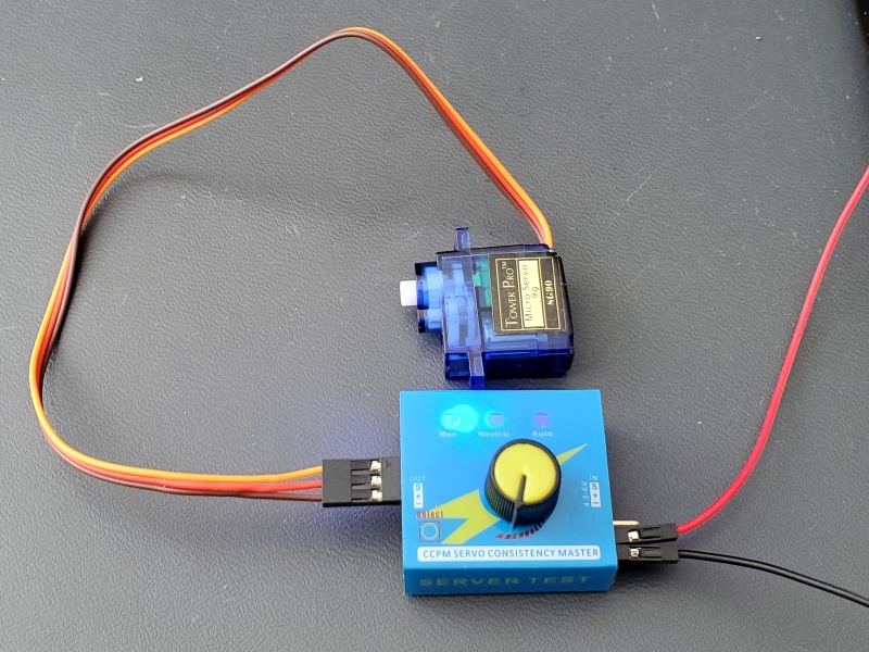
These are handy little devices for anyone that works with servos. They provide a simple way to test a servo to verify if it works or to exercise a servo built into a project such as a robotic arm without needing to do any programming. It can also be handy for embedding into a simple project such as a Halloween prop where you want the prop to continuously swing back and forth. They can also be used as a PWM input to an ESC (Electronic Speed Controller).
PACKAGE INCLUDES:
- Servo Tester Module
KEY FEATURES OF SERVO TESTER:
- 3 modes of operation
- Manual position mode using adjustment knob
- Return to center
- Auto sweep back and forth
- Output connectors for up to 3 servos
- Can use as input for ESC to test operation
- 4.8-6V operation and output pulse amplitude
Theory of Operation
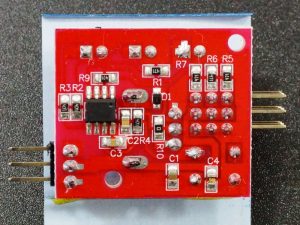
The 8-pin IC appears to be a microcontroller with the markings removed. There are a bunch of 470 ohm resistors for providing current limiting for the three LEDs as well as the three PWM outputs. The PWM outputs each have their own current limiting resistor, but they are all driven off the same signal.
The power and ground pins on the input side pass straight through to the power and ground pins on the servo connectors with a few filtering caps thrown in. Since the servos operate at 4.8 to 6V, the input needs to be fed with a power source between 4.8 and 6V.
Inputs
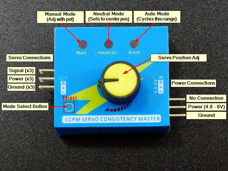
The input side is a 3-pin male header. Power is connected to ‘+‘ and ground is connected to ‘–‘. Current draw from the power supply will depend on the servo(s) being driven.
The ‘S’ (signal) pin on the input side is not connected to anything and can be left unconnected.
Outputs
The output is a 3×3 male header.
Up to 3 servos can be connected by a plugging the connectors in horizontally across the row of 3 pins. The servo brown (ground) wire goes to ‘–‘, the servo red (power) wire goes to ‘+‘ and the servo yellow/orange (signal) wire goes ‘S‘.
Modes of Operation
There are 3 modes of operation. The blue LEDs indicate the currently active mode and the SELECT button toggles between the different modes. When the device first powers up, the Manual mode is selected.
MAN – Manual Mode. Turning the knob controls the position of the servo. This is handy for testing the functionality of the servo in an application without having to setup an MCU with software. If a servo is connected to the elbow of a mechanical arm, the arm can be exercised through its range using the control knob.
NEUTRAL – Returns the servo to the center position.
AUTO – Runs the servo continuously through its full range left and right approximately once per second. This can be handy for testing servos over time or to automate the movement of a device such as a prop that needs to swing back and forth.
Note: This device is only designed to work with servos or as a PWM input to an ECS (Electronic Speed Control) unit. It is designed to drive a low current PWM output and simply pass power and ground through. It is not suitable to try to control DC motors directly using PWM as it cannot provide the necessary current.
Module Connections
Input
- – = Ground
- += Power (4.8 – 6VDC)
- S = No connect
Output to servo or ECS (x3)
- – = Ground
- += Power (4.8 – 6VDC)
- S = PWM Output
OUR EVALUATION RESULTS:
These are simple yet clever little boxes that can be quite useful. We use them to exercise servos back and forth for extended periods of time when we are doing basic testing or to experiment with motion of articulated assemblies without having to mess around with hooking up an MCU and writing code.
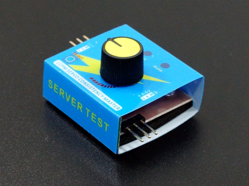
The packaging is an example of how to manufacture a device as cheaply as possible and it looks a bit like a plastic match box but it gets the job done.
The main criticism of the tester is that it will not necessarily exercise a servo through its full range of motion. To avoid overdriving servos it keeps the PWM within a safe range. That may mean that a 180° servo will only rotate 150° using this tester.
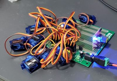
Here is a simple setup we made using one of these modules to exercise many servos at once. It was taken out of the packaging and the output pins were soldered into one of our prototyping boards. The module gets power through these output pins and the signal output is run to a row of header pins along with 5V and Gnd. Power is supplied from an external bench power supply.
Troubleshooting Tips
If the blue LEDs flicker during servo operation and the servo acts erratic, that generally indicates that the power to the unit doesn’t have enough current capability. We have seen this when we had the current limit set too low on our bench power supply.
If the device seems to reset on handling, it is usually due to intermittent power connections. We have seen this when using old breadboard jumpers that have gotten sloppy and tend to make intermittent contact when wiggled.
If the servo is a larger servo and seems to be responding poorly, ensure the power wiring isn’t dropping too much voltage. If the power supply is 5V, it is easy to get < 4.8V at the servo if using breadboard jumpers. In that case either use larger wiring to reduce the voltage drop or increase the 5V up to a maximum of 6V.
Below is a scope capture of a typical PWM waveform output with 5V power input.
BEFORE THEY ARE SHIPPED, THESE MODULES ARE:
- Sample inspected and tested per incoming shipment.
Notes:
- None
Technical Specifications
| Operational Ratings | ||
| Vcc | Range | 4.8 – 6VDC |
| Frequency | 49Hz measured (50Hz nominal) | |
| PWM Pulse Amplitude | Same as Vcc | |
| Dimensions | L x W x H w/out pins | 35 x 31 x 24mm (1.38 x 1.22 x 0.95″) |

