OLED 0.91″ 128×32 I2C White Display
$4.95
Small form factor with SSD1306 controller and I2C interface.
13 in stock
Description
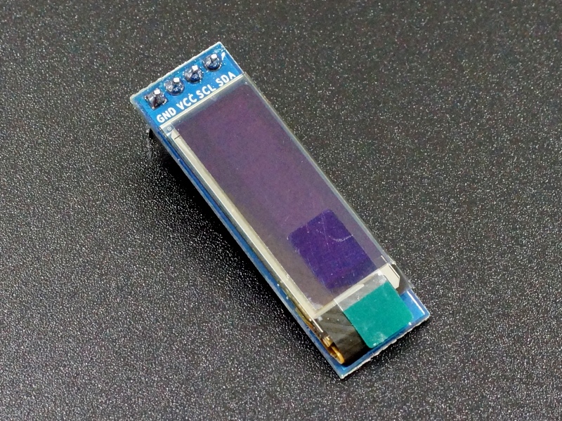
This 0.91″ OLED display has a resolution of 128 x 32 white pixels on a black background with an I2C interface for easy control by an MCU.
PACKAGE INCLUDES:
- OLED 0.91″ 128×32 I2C White Display
KEY FEATURES OF OLED 0.91″ 128×32 I2C WHITE DISPLAY:
- Latest OLED light emitting technology
- 128 x 32 pixel resolution
- White on black monochrome display
- I2C interface uses only 2 pins on MCU
- SSD1306 OLED controller
- 3.3 or 5V operation
These displays can pack a lot of information into a very small form factor.
OLED Display
OLED displays are the latest in display technology which is just now starting to be introduced in flat-panel televisions. They emit light without requiring a backlight and so have excellent viewing angle, brightness and contrast in a very thin and efficient package.
The display has a resolution of 128 x 32 pixels. The pixels are white on a black background.
The module uses the SSD1306 controller and is compatible with software libraries that support that controller.
One thing to note about OLEDs is that they are similar to the old Plasma TVs in that they can retain an image if they are left on continuously displaying the same image. They are best suited for applications where the screen is either turned off or the image is changed on occasion.
I2C Interface
This display incorporates an I2C interface that requires only 2 pins on the MCU to interface with and it has good library support to get up and running fast.
The default I2C address for these displays is 0x3C. The address is marked on the bag that the module comes in.
If you are unsure of the I2C address of this or any other device, it is easy to find out what it is. Just refer to this blog post.
Module Connections
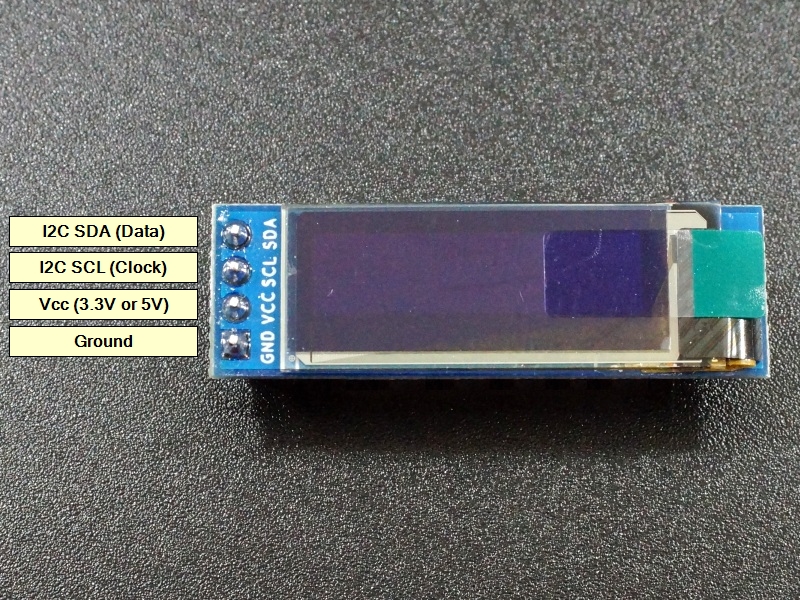
Connection to the display is via a 4 pin header.
1 x 4 Header
- GND – Connect to system ground. This ground needs to be in common with the MCU.
- VCC – Connect to 3.3 or 5V. This can come from the MCU or be a separate power supply.
- SCL – Connect to the I2C / SCL pin on the MCU.
- SDA – Connect to the I2C / SDA pin on the MCU.
OUR EVALUATION RESULTS:
These are interesting modules to work with since they have full graphical capability but can also pack a lot of textual information into a very small form factor.
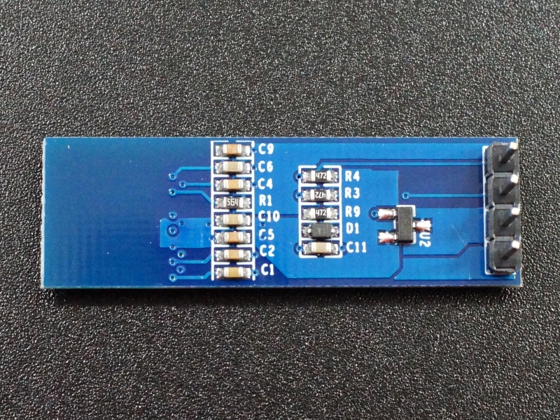
These modules are breadboard friendly with a 4-pin header on the back that can be inserted into a solderless breadboard or a 4-pin female connector can be used to connect to it if the display is to be mounted. The display is very thin, so be sure to press on the header pins when applying pressure to insert them into a breadboard and not press on the glass.
Follow these simple steps to get the display up and running.
Connect the display
This is simple, just connect VCC to 5V (or 3.3V) to match the MCU and connect GND to ground. The I2C lines just connect to the same lines on the MCU so SCL connects to SCL and SDA connects to SDA.
Install Libraries
Install the following 2 libraries if they are not already installed on your computer. These can be installed from within the Arduino IDE.
“Adafruit SSD1306”
“Adafruit GFX Library”
Download and run program
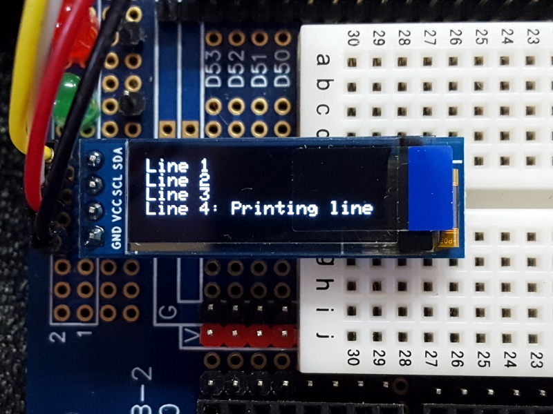
This program just prints some text to the display which is the most common use for the display. To see a demo of the full graphical capability, you can also run the sample program that is installed with the Adafruit SSD1306 library.
SSD1306 128 x 32 I2C Test Program
/**************************************************************************
SSD1306 128x32 I2C test

This simple program initializes the display and prints small text to
four different lines on the displays.

Connect display Vcc to 3.3 or 5V to match MCU and GND to ground
Connect display I2C SCL to MCU SCL and SDA to MCU SDA
 **************************************************************************/

#include <Wire.h>
#include <Adafruit_GFX.h>
#include <Adafruit_SSD1306.h>

#define SCREEN_WIDTH 128 // OLED display width, in pixels
#define SCREEN_HEIGHT 32 // OLED display height, in pixels

// Declaration for an SSD1306 display connected to I2C (SDA, SCL pins)
Adafruit_SSD1306 display(SCREEN_WIDTH, SCREEN_HEIGHT, &Wire);

//===============================================================================
//  Initialization
//===============================================================================
void setup() {
  Serial.begin(9600);

  // SSD1306_SWITCHCAPVCC = generate display voltage from 3.3V internally
  if(!display.begin(SSD1306_SWITCHCAPVCC, 0x3C)) { // I2C Address 0x3C for 128x32
    Serial.println(F("SSD1306 allocation failed"));
    for(;;); // Don't proceed, loop forever
  }

  // Clear the buffer, set small font size and print 4 lines of text to display
  display.clearDisplay();
  display.setTextSize(1);                    // Set for small font
  display.setTextColor(WHITE);
  display.setCursor(0,0);                    // Set cursor to upper left
  display.println("Line 1: Printing line");  // Println moves the cursor down
  display.println("Line 2: Printing line");
  display.println("Line 3: Printing line");
  display.println("Line 4: Printing line");

  // Show the display buffer on the screen. You MUST call display() after
  // drawing commands to make them visible on screen!
  display.display();
}
//===============================================================================
//  Main
//===============================================================================
void loop() {
}
BEFORE THEY ARE SHIPPED, THESE MODULES ARE:
- Inspected
- Functionality tested
- Repackaged in high quality resealable ESD bag for safe storage.
Notes:
- The display is thin and fragile. Ensure you don’t apply pressure directly to the glass or it may crack.
Technical Specifications
| Display | Resolution | 128 x 32 pixels |
| Color | White (monochrome) | |
| Interface | I2C (Address 0x3C) | |
| Operating Ratings | DC Power Input | 3.3 or 5V |
| Operating Current | <1mA (typical) | |
| Dimensions | ||
| Module Size (L x W) | 38 x 12mm (1.5 x 0.47″) | |
| Display diagonal | 23mm (0.91″) | |
| Display (W x H) | 22.38 x 5.52mm (0.88 x 0.22″) | |
| Display Controller | SSD1306 |


