


NEO-6M GPS Module
$12.95
Low cost and easy to use GPS module
4 in stock
Description
The u-blox NEO-6M module is a low cost easy to use GPS module that includes a built-in antenna.
PACKAGE INCLUDES:
- NEO-6M GPS Module
- 1×5 male header strip
KEY FEATURES OF NEO-6M GPS MODULE:
- USB interface
- Serial interface via header
- On-board ceramic antenna
- LED indicates power and successful satellite time lock
- Battery backup for fast hot restart
- 1 second navigation update rate
- 5V power
- 3.3V logic compatible
Working with GPS (Satellite Positioning System) can seem intimidating, but this easy to use module along with the u-blox free u-center for Windows software makes it easy to get up and running with a graphical interface to see the module functioning by plugging in a micro-B USB cable.
The module also has a connector location for connecting to power and serial lines on an MCU for a home brew setup.
USING WITH U-CENTER SOFTWARE:
The company u-blox that makes the NEO-6M GPS core module provides a free to use Windows application software for interfacing with their products. This tool provides a great amount of graphical information and is recommended as a good way to explore the ins-and-outs of working with GPS modules and verify operation even if the intent is to eventually hook it up to an microcontroller.
The u-center User Guide can be found here: https://www.u-blox.com/sites/default/files/u-center_Userguide_UBX-13005250.pdf
The u-center software for Windows can be downloaded from the following link. You want the u-center and not the u-center-2 download: https://www.u-blox.com/en/product/u-center
Once downloaded, extract and execute the downloaded .exe file. The installer will walk you through a couple of steps to install the software correctly and open the application.
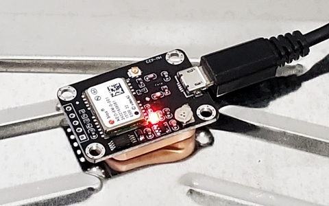
Plug the NEO-6M module into a Micro-B USB connector that is connected to your computer. The red LED on the module will come on steady showing that it has power but no satellite lock.
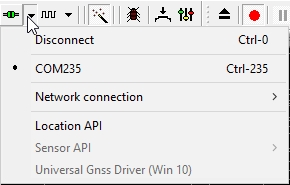
To link to the module and see it doing something, locate the communication toolbar on the left side and click on the arrow next to the communication icon.
![]()
Select the COM port that the module is connected to. In our example it is COM235
Next click on the arrow adjacent to the square wave looking icon which signifies baud rate and verify that it is set for 9600 which is the default speed for this module.
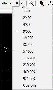
The communication icon will turn green to show that communications has been established with the NEO-6M module.
Once the module receives power, it will be looking for satellites on its own and communicating what it finds to the u-center software. If it can find at least one and get a valid time sync from the satellite, the LED will start to blink at a one second rate. This LED is connected to the PPS pin which is also available on the header connector. While it can get the time from a single satellite, it needs to find several satellites in order to triangulate and calculate things such as longitude, latitude and altitude.
The image below shows the u-center software with several windows open. These include a Deviation Map that shows the accuracy of the positioning, Sky View showing the satellites it can see, Satellite level which shows the signal strength from each satellite and World Position which is a map of the world with the location of the device marked. Hopefully that mark is somewhere close to where you are located. There are many other windows available including console views that show the text communications, altitude, time, etc.
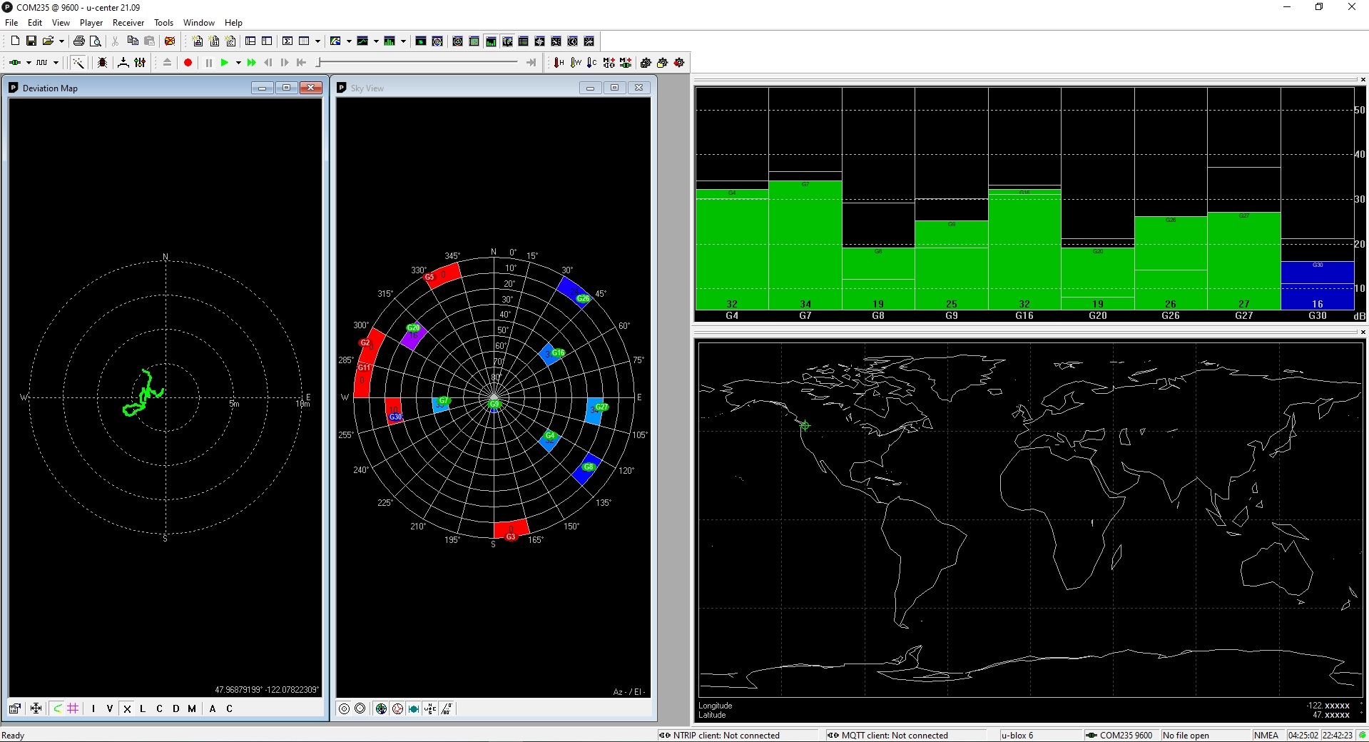
When first powered up, the module may take 5-10 minutes to get an initial lock and for the LED to start blinking. The module needs to receive a signal of about 26dB as shown in the Satellite Level window to lock on. Once locked, the signal strength can be less and still maintain lock. There is a small rechargeable battery on the module. Once charged, it allows the module to lose power for a period of time and then quickly re-establish lock once power is reapplied.
If the LED does not blink, check/do the following:
- Ensure the module is placed so that the antenna is parallel to the horizon for best reception.
- If the module is in a building, move it closer to a window. The module needs a direct line of sight to the satellites and depending on building construction, it may or may not work well inside.
- Move the module outside where it has an unobstructed view of the sky. It doesn’t need to be hooked up to a computer to see if that is the problem. If you supply 5V power and ground to the module and it can find satellites, the LED will start to blink.
- If you have been playing with it for some time without a lock even though the signal strength seems sufficient, sometimes selecting FILE / DATABASE EMPTY seems to help it achieve lock or at least it updates the display so that it shows a lock has been acheived.
- Place it on a ground plane. Placing the module on a piece of sheet metal with the ceramic antenna facing down will help increase the signal strength and achieve lock. This can be a pretty good hack when working indoors. We have used a metal paint tray (because it was the first piece of metal we found in the garage) and achieved 5dB of gain. A 6″ metal plate on a small scale or upturned paint can gave similar results This was enough to move from very intermittent operation to allowing us to use the modules reliable indoors. The Satellite Level window is very handy for seeing the effects of changes such as placing the module on a ground plane.
The module also has a U_FL style connector. Presumably this would allow the module to be used with an external active antenna to increase sensitivity, but this has not been tried and it is unclear how it would act with having two antenna attached at the same time.
USING WITH A MICROCONTROLLER
When using with an microcontroller, you will need to connect 5V power and ground to the module. The NEO-6 device operates at 3.3V and the module includes a 3.3V regulator. It will not operate from 3.3V power.
Communication with the module is via the serial TX/RX lines. The TX of the module connects to the RX pin on the MCU and the RX pin on the module connects to the TX pin on the MCU. For basic operation which simply reads the data stream coming from the device, only the TX pin of the module needs to be connected to an RX pin on the MCU. This can be a direct connection whether the MCU is 3.3V or 5V. If you want to configure the module by writing to it, the RX pin can also be connected. If using with a 3.3V MCU, this can be a direct connection, but if using with a 5V MCU, a level shifter must be used to avoid possible damage to the module.
Either software or hardware serial connections can be used.
There are many libraries available for working with these modules. The TinyGPSPlus (also called TinyGPS++) works well and have a number of good examples. It can be downloaded from the IDE Library Manager.
Module Connections
The module has a micro-B USB connector for direct connection to a computer.
The module also has a header location for connecting to a microcontroller. A male header is supplied which can be soldered to this location on either side of the board, or a female header or wires can also be used.
1×5 Header
- VCC = Module power (5V)
- GND = Ground for module power
- RXD = Serial receive data input to module
- TXD = Serial transmit data output to MCU
- PPS = Time Pulse is an output which pulses at one second rate to indicate time sync with a satellite. Signal is also connected to on-board LED
OUR EVALUATION RESULTS:
These are very interesting modules that can be quite fun to play with. The u-center software makes it easy to quickly see the module functioning and allows you to explore the device functionality much easier than by hooking it straight up to an MCU and then wondering why nothing is happening.
Integration with an MCU is also fairly straightforward for such a complex device with one of the many libraries that are available.
BEFORE THEY ARE SHIPPED, THESE MODULES ARE:
- Basic satellite lock operation verified using the u-center software
- Packaged in a resealable ESD bag for protection and easy storage.
Notes:
- None
Technical Specifications
| Operational Ratings | ||
| Vcc | 5V | |
| Current Draw | 80mA (typ) | |
| Logic Compatibility | 3.3V | |
| Max Navigation Update Rate | 1 second | |
| Dimensions | ||
| PCB (L x W) | 38 x 26mm (1.5 x 1″) | |
| Height | 8.5mm (0.34″) | |
| Country of Origin | China | |
| Datasheet | u-blox | NEO-6M |