MPU-6050 GY-521 3-Axis Accel & Gryo Sensor Module
$2.95
Combines 3-axis accelerometer and gyroscope packaged in low cost module.
8 in stock
Description
The MPU-6050 combines a 3-axis accelerometer and 3-axis gyroscope with an on-board Digital Motion Processor (DMP) packaged in a low cost GY-521 module.
PACKAGE INCLUDES:
- MPU-6050 GY-521 3-Axis Accel & Gryo Sensor Module
- 8-pin male header straight
- 8-pin male header right-angle
KEY FEATURES OF MPU-6050 GY-521 3-AXIS ACCEL & GRYO SENSOR MODULE:
- 3-axis MEMS 16-bit accelerometer with programmable range
- 3-axis MEMS 16-bit gyroscope to detect rotation with programmable range
- 9-axis MotionFusion Digital Motion Processor (DMP)
- Temperature sensor range of -40 to +85C
- Interrupt output
- I2C Interface
- 5V operation (built-in 3.3V regulator powers MPU-6050 device)
The MPU-6050 is a low-cost accelerometer & gyroscope option for use in applications such as gesture recognition in gaming, self-balancing robots, toys, cell phones, vehicle navigation, fitness monitoring and similar applications where detection of movement direction and magnitude along with rotation is desired.
Both the accelerometer and gyroscope each makes use of three 16-bit ADCs with four programmable ranges for high sensitivity. A built-in temperature sensor is also provided for measuring the chip die temperature and has a wide measurement range from -40C to +85C.
Communications between the sensor and the MCU is done over the I2C interface.
The MPU-6050 sensor operates at 3.3V. but the GY-521 module contains a 3.3V regulator so the module should be supplied with 5V on the VCC pin. Since the module uses I2C which is open-drain with pull-ups to 3.3V, level translation is generally not considered necessary when using it with a 5V MCU.
The module is relatively easy to get up and running and capturing the raw data output of the device. Manipulating the data into something meaningful is more of a challenge, but there are some good libraries available for using the device.
Measuring Temperature
The MPU-6050 can measure temperature over the range of -40 to 85°C.
The measurement is of the die itself and will typically be near ambient. This temperature can be used to offset the calibration of the accelerometer and gryo or can provide a general indication of the ambient temperature and temperature changes.
Accuracy is about ±1°C over the entire range.
Measuring Acceleration
The MPU-6050 can measure acceleration using its on-chip accelerometer with four programmable full scale ranges of ±2g, ±4g, ±8g and ±16g that can be set by the user.
The integrated 16-bit ADCs simultaneously sample the 3 axis of movement (X, Y, Z).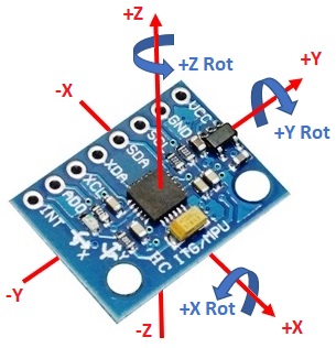
The X, Y and Z are relative to how the chip sits on the module as shown to the right and will ultimately be dependent on the orientation of the module in your project.
Initial calibration tolerance is ±3% with non-linearity typically 0.5%.
Measuring Rotation
The MPU-6050 can measure rotation using its on-chip gyroscope with four programmable full scale ranges of ±250°/s, ±500°/s, ±1000°/s and ±2000°/s that can be set by the user.
The integrated 16-bit ADCs simultaneously sample the 3 axis of rotation around the X, Y and Z axes. The sample rate can be adjusted from 3.9 to 8000 samples per second.
The axis of rotation are relative the the X, Y and Z shown to the right.
Digital Motion Processor (DMP)
The MPU-6050 has an embedded Digital Motion Processor that can be used to off-load computation of motion processing algorithms from the MCU, freeing it up to be doing other things.
It uses the data from the accelerometer, gyroscope and even external sensors such as magnetometers. It can process it at high speed and make it available to the host MCU.
Using the I2C Interface
The module uses the I2C interface for communications with the MCU. It supports two different I2C addresses; 0x68 and 0x69. That allows two devices to be used on the same bus or in case there is an address conflict with another device on the bus.
The ADO pin determines the I2C address to use. This pin has a built-in 4.7K pull-down resistor on the module. If the pin is left unconnected, the line will be pulled low and the default I2C address will be 0x68. To select 0x69, connect the ADO pin to 3.3V.
The SCL and SDA pins connect to the SCL and SDA pins on the MCU.
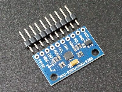
Module Connections
The module brings out the following connections.
1 x 7 Header
- VCC = 5V nominal. Connect to 5V output of the MCU
- GND = Ground
- SCL = Clock (SCL / SCK) for I2C and SPI
- SDA = Data (SDA / SDI) for I2C and SPI
- XDA = Auxillary I2C bus (SDA) for connecting external sensors
- XCL = Auxillary I2C bus (SCL) for connecting external sensors
- ADO = Address select for I2C
- INT = Interrupt Output
Module Assembly
The module ships with the male header strips loose for flexibility. The straight or right-angle header can be soldered to the top or bottom of the module depending on the planned use or wires can be used to make the connections which may be desirable in some final applications.
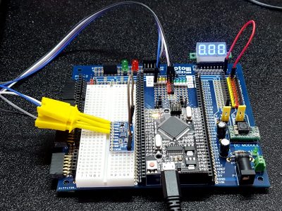
For breadboard use, we put the straight header on the bottom. Soldering is easiest if the header is inserted into a solderless breadboard to hold it in position during the soldering process.
OUR EVALUATION RESULTS:
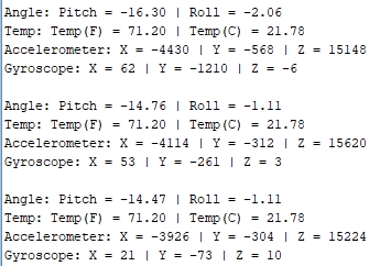
The program below continually reads the sensor and reports the raw accelerometer, gyroscope and temperature data. It also calculates and reports the angle of pitch and roll.
This program uses built-in libraries to communicate with the device to keep things simple for testing purpose. For live applications, there are a number of libraries available which can be handy for adding advanced functionality.
To test the device, simply connect VCC to 5V, GND to ground and the SDA and SCL pins to the same on the MCU. Download the example program and open the Serial Monitor window to see the output.
If the device is tilted, the pitch and roll numbers should reflect the angle at which the device tilted.
Note that the program provides data correction off-sets for the readings that can be used to help calibrate the device. If the device is kept motionless, the accel and gyro readings will be bouncing around, but should be close to 0. The data correction offset values can be adjusted to bring these numbers closer to 0. If a reading is hovering around -1000, the offset can be set to +1000 to help bring it toward 0.
In some of the links below, there is information on programs that can be run which will help provide these calibration off-sets by taking the average over many samples.
MPU-6050 Example Program
/*
   MPU-6050 Test

   This simple program reads and prints to the Serial Monitor window
   the raw X/Y/Z values for the accelerometer and the gyro
   It also calculates the pitch and roll values as well as the temperature
   in F and C.

   Connect VDD to 5V and GND to ground on the MCU
   Connect SCL to SCL on MCU and SDA to SDA on MCU

  Note that the correction values can be used to put in an offset to adjust the
  values toward 0 or in the case of the temperature to adjust it to match a
  reference temperature measurement device.
*/
#include<Wire.h>
#include <math.h>
const int MPU=0x68;
int16_t AcX,AcY,AcZ,Tmp,GyX,GyY,GyZ;
double pitch,roll;
//===============================================================================
//  Initialization
//===============================================================================
void setup(){
Wire.begin();
Wire.beginTransmission(MPU);
Wire.write(0x6B);
Wire.write(0);
Wire.endTransmission(true);
Serial.begin(9600);
}
//===============================================================================
//  Main
//===============================================================================
void loop(){
Wire.beginTransmission(MPU);
Wire.write(0x3B);
Wire.endTransmission(false);
Wire.requestFrom(MPU,14,true);

int AcXoff,AcYoff,AcZoff,GyXoff,GyYoff,GyZoff;
int temp,toff;
double t,tx,tf;

//Acceleration data correction
AcXoff = -250;
AcYoff = 36;
AcZoff = 1200;

//Temperature correction
toff = -1400;

//Gyro correction
GyXoff = -335;
GyYoff = 250;
GyZoff = 170;

//read accel data and apply correction
AcX=(Wire.read()<<8|Wire.read()) + AcXoff;
AcY=(Wire.read()<<8|Wire.read()) + AcYoff;
AcZ=(Wire.read()<<8|Wire.read()) + AcZoff;

//read temperature data & apply correction
temp=(Wire.read()<<8|Wire.read()) + toff;

//read gyro data & apply correction
GyX=(Wire.read()<<8|Wire.read()) + GyXoff;
GyY=(Wire.read()<<8|Wire.read()) + GyYoff;
GyZ=(Wire.read()<<8|Wire.read()) + GyZoff;

// Calculate and convert temperature
tx=temp;
t = tx/340 + 36.53;     // Formula from data sheet
tf = (t * 9/5) + 32;    // Standard C to F conversion

//get pitch/roll
getAngle(AcX,AcY,AcZ);

//send the data out the serial port
Serial.print("Angle: ");
Serial.print("Pitch = "); Serial.print(pitch);
Serial.print(" | Roll = "); Serial.println(roll);

Serial.print("Temp: ");
Serial.print("Temp(F) = "); Serial.print(tf);
Serial.print(" | Temp(C) = "); Serial.println(t);

Serial.print("Accelerometer: ");
Serial.print("X = "); Serial.print(AcX);
Serial.print(" | Y = "); Serial.print(AcY);
Serial.print(" | Z = "); Serial.println(AcZ);

Serial.print("Gyroscope: ");
Serial.print("X = "); Serial.print(GyX);
Serial.print(" | Y = "); Serial.print(GyY);
Serial.print(" | Z = "); Serial.println(GyZ);
Serial.println(" ");
delay(333);
}
//===============================================================================
//  GetAngle - Converts accleration data to pitch & roll
//===============================================================================
void getAngle(int Vx,int Vy,int Vz) {
double x = Vx;
double y = Vy;
double z = Vz;
pitch = atan(x/sqrt((y*y) + (z*z)));
roll = atan(y/sqrt((x*x) + (z*z)));
//convert radians into degrees
pitch = pitch * (180.0/3.14);
roll = roll * (180.0/3.14) ;
}
BEFORE THEY ARE SHIPPED, THESE MODULES ARE:
- Sample inspected and basic operation verified
Notes:
- If you are looking for a device that also has a built-in magnetometer which provides compass navigation, check out the MPU-9250 below.
Technical Specifications
| Operating Ratings | ||
| Vcc | Module | 5V (typical) |
| Accelerometer | Ranges | ±2g, ±4g, ±8g, ±16g |
| Gyroscope | Ranges | ±250°/s, ±500°/s, ±1000°/s, ±2000°/s |
| Temperature | Range | -40 to +85°C |
| Shock Tolerance | Max | 10,000g |
| Dimensions | L x W (PCB) | 21 x 16mm (0.8 x 0.63″) |
| Country of Origin | China | |
| Datasheet | TDK InvenSense | MPU-6050 |
FURTHER READING
Good overview of the MPU-6050 device: http://playground.arduino.cc/Main/MPU-6050
Advanced library for MPU-6050: https://github.com/jrowberg/i2cdevlib/tree/master/Arduino/MPU6050
Download library here: https://github.com/jrowberg/i2cdevlib
Good write-up on using library: http://www-robotics.cs.umass.edu/~grupen/503/Projects/ArduinoMPU6050-Tutorial.pdf