0.39″ Mini DVM 0-100 VDC 3-Wire Yellow
$3.95 – $4.95
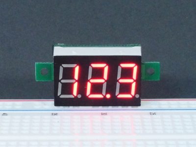
Miniature voltmeter for monitoring voltages on a breadboard or for embedding into project.
Description
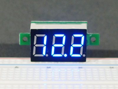
The Mini DVM 0-100VDC 3-Wire Yellow is a miniature voltmeter perfect for monitoring voltages on a breadboard or for embedding into your project.
PACKAGE INCLUDES:
- Mini DVM 0-100VDC 3-Wire Yellow
KEY FEATURES OF MINI DVM 0-100VDC 3-WIRE YELLOW:
- Measures voltages from 0 to 99.9V
- Device can be powered from voltage being measured or from different voltage
- 1 digit typical accuracy with calibration pot available
- Yellow display color
- Optional lead terminations
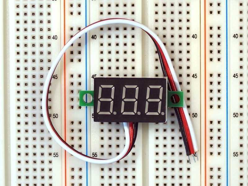
- Stripped leads (standard)
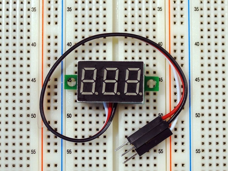
- Male Dupont jumper pins (installed optionally)
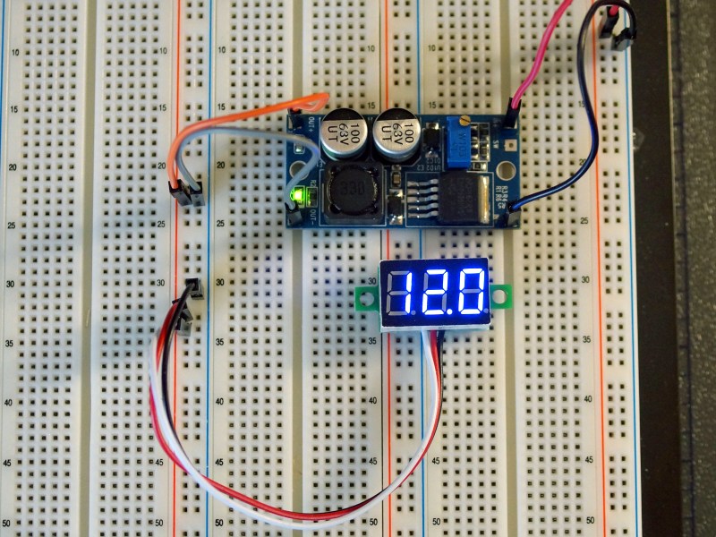
This miniature volt meter is perfect for adding to your breadboard or project to keep track of a voltage such as monitoring a battery or to allow for easy adjustment of a variable DC-DC converter or variable linear regulator circuit without needing to break out your bench DVM each time.
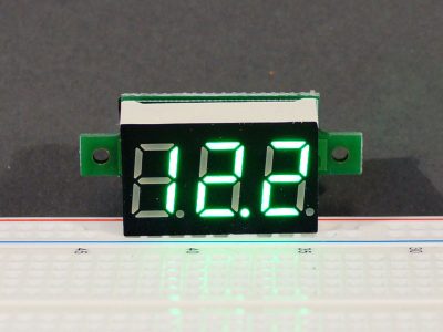
The displays are available in red, green, yellow and blue. When ordering, the leads can be selected as standard with stripped wire ends which is useful if the display will be soldered or otherwise permanently mounted. For solderless breadboard applications, the displays are also available with male jumper pins installed so that they are ready to plug-n-play.
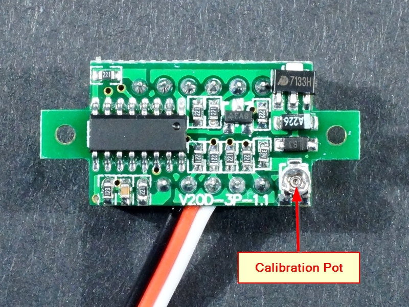
The device is designed around a small microprocessor with built-in A/D converter, oscillator and 7-Seg LED driver capability. Accuracy is good over the specified range and adequate for most applications that you will find this useful in. Typically the reading will be within 1 digit, so 5.0V may read 4.9 to 5.1V There is a small pot on the back of the assembly which allows you to tweak the calibration if you so desire and have access to another voltmeter to reference it against.
The maximum reading that can be displayed is 99.9V. When first measuring a voltage, it may take a couple of update cycles for the display to lock onto the final reading.
DVM Connections
These voltmeters are 3-wire for maximum flexibility. Two wires are used for power and the third wire is used for sensing the voltage.
The wire leads come out between the LED and PCB. This helps to make the device more durable as it strain-relieves the leads so they won’t break off as easily if you decide to use it as a fidget-spinner while pondering your next great design!
To hookup, simply connect the black wire to ground, the red wire to a positive power supply anywhere from 3 to 30VDC and the white (sense) wire to the voltage that you wish to monitor.
If you are monitoring the power supply that you have the volt meter powered off of, you can simply hook both the red and white wires up to the same positive voltage as long as the power supply is operating in the range of 3- 30V.
The module will draw 10-23mA depending on the operating voltage and the color of the display. If you are using it to monitor a low current (high impedance) voltage source, you may need to power it off a different power source to avoid loading the source your are monitoring too much. When powering from a separate voltage, the white measurement lead only draws about 40uA from the circuit.
If you want to measure voltages < 3.0VDC, you will need to power the voltmeter off of a separate power source as the LED display will start to dim once the supply voltage starts to drop below that level. No harm will come to the device if this happens, but a voltmeter without a display isn’t very useful. Similarly, if you want to measure voltages greater than 30V, you will also need to power the voltmeter off of a separate power source to avoid damage to the voltmeter.
OUR EVALUATION RESULTS:
These are very useful modules that can be applied to a number of different applications.
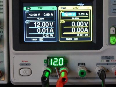
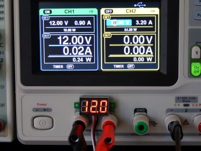
I find a use for these in many projects or for test setups like testing and adjusting DC-DC converters. When working with a solderless breadboard, it can often be more convenient to wire one of these into a circuit that you want to keep an eye on than to keep getting a DVM out and probing the circuit.
If I am using a variable or several different voltages on solderless breadboard power rails, I like to hook one or two of these up to the rails to help me remember what voltage I have running on the rails so I don’t accidentally fry something by plugging it into the wrong rail.
BEFORE THEY ARE SHIPPED, THESE MODULES ARE:
- Inspected
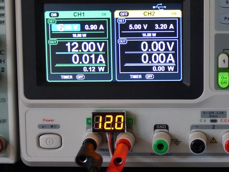
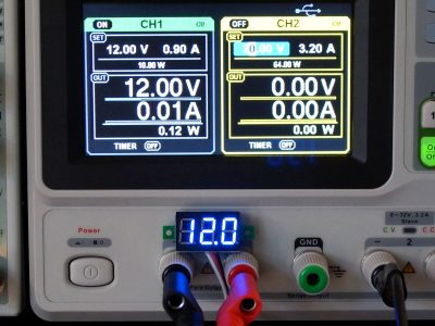
- Accuracy verified at 12.0V (+/- 0.1V)
- Solderless breadboard pins added if requested.
Notes:
- The back of the board contains the electronics, so some care should be used to avoid possible shorting if placed on a metallic surface.
- Power leads (red/black) have reverse polarity protection. If the display doesn’t light up, be sure to check that you don’t have the polarity reversed.
- There is a small 3-lead regulator on the back of the meter. This device can get pretty warm when operating the device off higher voltages.
Technical Specifications
| Display | Color | Yellow (other colors available) |
| Update Rate | 500mS (approx) | |
| Operating Power (Red Wire) |
DC Power Input range | 3 – 30VDC |
| DC Power Draw (Varies with display color and digits being displayed) |
Red < 23mA Yellow < 21mA Green < 15mA Blue < 13mA |
|
| Reverse polarity protection | Yes | |
| Measurement (White Wire) |
DC Measurement Range (with external power) | 0-99.9VDC |
| DC Measurement Range (when measuring same voltage as powers the device) | 3 – 30VDC | |
| Accuracy | ±1% (± 1 digit) | |
| Calibration | Pot on back can be used to recalibrate | |
| Signal Loading | 125kOhm (40uA @ 5V) | |
| Dimensions | PCB w/ mounting ears | 33 x 15mm (1.3 x .55″) |
| Mounting Hole Distance | 28mm (1.1″) | |
| Mounting Hole Diameter | 1.85mm (0.072″) | |
| Display Size w/out mounting ears | 24 x 15mm (0.87 x 0.6″) | |
| Display Height w/ PCB | 10mm (0.39″) (typical) | |
| Character Height | 9.14 mm (0.36″) | |
| Lead Length | 150 mm (~6″) | |
| Module Weight | 5.1g | |
| Environment | -10° to 65°C (14°-149°F) |
You may also like…
-
Select options This product has multiple variants. The options may be chosen on the product page
0.39″ Mini DVM 0-100VDC 3-Wire Blue
$3.95 – $4.95Miniature voltmeter for monitoring voltages on a breadboard or for embedding into project.
-
Select options This product has multiple variants. The options may be chosen on the product page
0.39″ Mini DVM 0-100VDC 3-Wire Green
$3.95 – $4.95Miniature voltmeter for monitoring voltages on a breadboard or for embedding into project.
-
Select options This product has multiple variants. The options may be chosen on the product page
0.39″ Mini DVM 0-100VDC 3-Wire Red
$3.95 – $4.95Miniature voltmeter for monitoring voltages on a breadboard or for embedding into project.


