MIC5891 High Voltage 8-Bit Shift Register
$2.79
High-side 8-Bit Shift Register for driving high voltage and high current devices
Out of stock
Description
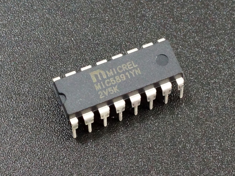
The MIC5891 is a high-side 8-Bit Shift Register useful for driving high voltage and high current common cathode 7-Segment displays and other devices.
PACKAGE INCLUDES:
- MIC5891 high voltage 8-Bit Shift Register
KEY FEATURES OF MIC5891 HIGH VOLTAGE 8-BIT SHIFT REGISTER:
- Used to expand output I/O capability of uC to drive high power devices
- 8-Bit Serial In / Parallel Out
- High-side operation
- 50V @ 500mA drive capability
- 5V compatible
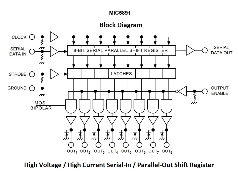
The MIC5891 is similar in functionality to the common 74HC595 except each output latch has a Darlington transistor open emitter driver that can source up to 500mA at up to 50V so it can directly drive high power loads.
Since it is designed to source current it can operate on the high side of loads. It is particularly well suited for driving larger high voltage common cathode 7-segment or other LED displays but can also drive relays and similar loads. It has built-in suppression diodes to protect against inductive load transients.
Data is shifted in serially and then latched on the chips 8 output pins in parallel. Multiple chips can be daisy-chained together if more outputs are needed. In addition, the chips can be run in parallel for increased current handling.
A single channel can handle up to a maximum of 50V@500mA. The maximum per channel overall will depend on how many channels are being used and the duty cycle that the channel is being switched at. Table 1-1 in the datasheet provides more guidance on this. If necessary, multiple chips can be run in parallel to increase the current handling capability.
The part can operate from 4.5- 15V on the logic supply and 5V – 50V on the load supply and is 5V logic compatible.
These parts are the DIP version so they are breadboard friendly.
Our Evaluation Results:

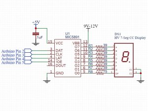
The example shown here happens to be using an 4″ 7-Segment common cathode display (XDMR-100C) that requires about 7.2V to operate. The program below simply cycles through all hex digits 0 thru F while also cycling the brightness of the display from max brightness to off.
The Vbb load supply voltage for the LED and the current limiting resistor values can be adjusted for the display being used.
For driving additional displays, the MIC5891 can be daisy-chained together with the SERIAL DATA OUT connecting to the SERIAL DATA IN on the next device.
In the example, we are using digital pins 2 thru 5 for connecting to the MIC5891. These can be any 4 digital pins except that OE_PIN needs to be a PWM capable pin.
MIC5891 High Voltage 8-Bit Shift Register Example Program
/*  MIC5891 Test
 *  Simple example of using MIC5891 HV Shift Register with a
 *  large Single Digit Common Cathode Seven Segment LED Display
 *  It cycles through displaying 0-F while also changing the
 *  brightness of the display using PWM
 *  Use appropriate series current limiting resistors on output pins.
*/
// Globals
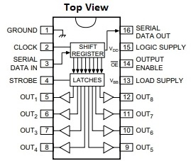
const int DATA_PIN = 2;  // Connect to MIC5891 pin 3
const int CLOCK_PIN = 3; // Connect to MIC5891 pin 2
const int LATCH_PIN = 4; // Connect to MIC5891 pin 4
const int OE_PIN = 5;    // Connect to MIC5891 pin 14

bool decimalPt = true;  // decimal point display flag
int pwmValue = 0;       // PWM brightness value
//===============================================================================
//  Initialization
//===============================================================================
void setup() {
  pinMode(DATA_PIN, OUTPUT);    // initialize I/O pins
  pinMode(LATCH_PIN, OUTPUT);
  pinMode(CLOCK_PIN, OUTPUT);
  pinMode(OE_PIN, OUTPUT);
  digitalWrite(OE_PIN, LOW);   // Enable MIC5891 outputs
  Serial.begin(9600);         // Initialize serial port
}
//===============================================================================
//  Main
//===============================================================================
void loop() {
  decimalPt = !decimalPt; // display decimal point every other pass through loop

  for (int i = 0; i <= 15; i++) {    // generate Hex characters to display (0 to F)
    byte bits = NumberToBits(i) ;
    if (decimalPt) {
      bits = bits | B10000000;      // add decimal point on every other pass
    }
    UpdateDisplay(bits);            // display alphanumeric digit
    delay(1000);                    // pause for 1 second
    analogWrite(OE_PIN, pwmValue);  // Change brightness of display
    pwmValue += 5;
    if (pwmValue > 255) pwmValue = 0; // The PWM logic is inverted, so 0 = max brightness
    Serial.println(pwmValue);
  }
}
/*
 * This subroutine uses shiftOut to shift the data into the MIC5891 and then
 * latches it on the output to update the display
 */
void UpdateDisplay(byte eightBits) {
  digitalWrite(LATCH_PIN, LOW);  // prepare shift register for data
  shiftOut(DATA_PIN, CLOCK_PIN, LSBFIRST, eightBits); // send data
  digitalWrite(LATCH_PIN, HIGH); // update display
}
/*
 * This subroutine uses a simple switch/case statement to convert the number (0-15)
 * to the outputs needed to drive the 7-seg display segments to form the numbers
 */
byte NumberToBits(int someNumber) {
  switch (someNumber) {
    case 0:
      return B00111111;
      break;
    case 1:
      return B00000110;
      break;
    case 2:
      return B01011011;
      break;
    case 3:
      return B01001111;
      break;
    case 4:
      return B01100110;
      break;
    case 5:
      return B01101101;
      break;
    case 6:
      return B01111101;
      break;
    case 7:
      return B00000111;
      break;
    case 8:
      return B01111111;
      break;
    case 9:
      return B01101111;
      break;
    case 10:
      return B01110111;  // Hexidecimal A
      break;
    case 11:
      return B01111100;  // Hexidecimal B
      break;
    case 12:
      return B00111001;  // Hexidecimal C
      break;
    case 13:
      return B01011110;  // Hexidecimal D
      break;
    case 14:
      return B01111001;  // Hexidecimal E
      break;
    case 15:
      return B01110001;  // Hexidecimal F
      break;
    default:
      return B01001001;  // Error: Displays three vertical bars
      break;
  }
}
Notes:
- None
Technical Specifications
| Maximum Ratings | Logic Operating Voltage Range | 4.5 – 15V |
| Load Operating Voltage Range | 5.0 – 50V | |
| Continuous Collector Current | 500mA | |
| Package | Footprint | DIP-16 |
| Type | Plastic, thru-hole | |
| Mfr | Microchip | |
| Datasheet | MIC5891 |


