Mercury Tilt Switch Module
$0.95
This module detects when it is tilted by way of liquid mercury making or breaking contact with switch electrodes.
Out of stock
Description
The Mercury Tilt Switch Module detects when the module is tilted by way of liquid mercury making contact with switch electrodes.
PACKAGE INCLUDES:
- Mercury Tilt Switch Module
KEY FEATURES OF MERCURY TILT SWITCH MODULE:
- Outputs logic HIGH or LOW depending on how module is tilted.
- Built-in 10K pull-up resistor
- LED indicates state
- 3.3 and 5V compatible
This module incorporates a small amount of conductive liquid mercury in a glass housing. The ball of mercury rolls through the housing and makes or breaks contact with switch electrodes as the module is tilted. With the glass end of the module held low, the contacts are open and a 10K pull-up resistor pulls the output HIGH. If the glass end of the module is raised, the mercury closes the contacts and the output is grounded and goes LOW. When the output is LOW, an on-board LED lights.
Module Connections
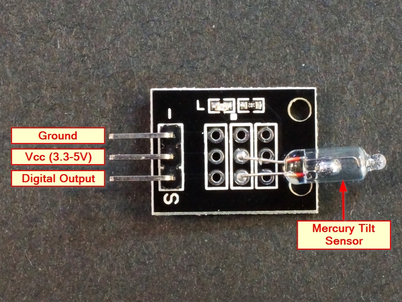
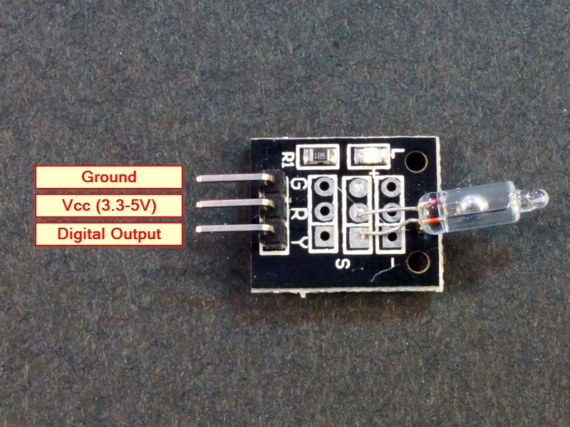
There is a 3-pin header on the assembly. There are a couple of different pin-out labels. See pics for clarification.
1 x 3 Header
- G / – = Ground
- R / Center pin = Vcc (3.3 – 5V)
- Y / S = Switch output. Connects to digital input pin on uC
OUR EVALUATION RESULTS:
This is a basic module that can be used to experiment with taking some action if the module is tilted. To test the basic module functionality, simple hook up power and ground and tilt the module to get the red LED to turn on and off.
The simple program below goes one step farther and prints out whether the current state of the switch output is logic HIGH or LOW. The switch output is connected to pin 4 in the example, but it can be any digital pin.
Mercury Tilt Switch Module Test Program
/*
Mercury Tilt Switch Module Test

Basic code enabling monitoring the output of the tilt module.
*/

int switchPin = 4; // select a digital pin for detecting the position of the switch
int state = 0;    // Current state of the tilt switch
//===============================================================================
//  Initialization
//===============================================================================
void setup()
{
  pinMode (switchPin, INPUT);
  Serial.begin (9600);      // Set output window comm rate
}

//===============================================================================
//  Main
//===============================================================================
void loop()
{
  state = digitalRead (switchPin);

  Serial.print ("Current Switch State: ");
  Serial.println (state);

  delay(1000);
}
BEFORE THEY ARE SHIPPED, THESE MODULES ARE:
- Inspected
- Basic operation verified
- Packaged in a resealable ESD bag for protection and easy storage.
Notes:
- This is similar to or the same as the KY-17 module.
Technical Specifications
| Operating Ratings | Vcc Range | 3.3 – 5V |
| Logic high | Pulled to Vcc | |
| Logic Low | Pulled to Ground | |
| Dimensions | L x W (PCB) | 19 x 16mm (0.75 x 0.6″) |


