MAX9812L Microphone Amplifier Module
$4.95
This module incorporates a microphone and the MAX9812L audio amplifier IC in a compact easy to use package
Out of stock
Description
This module incorporates a microphone and the MAX9812L audio amplifier IC in a compact easy to use package
PACKAGE INCLUDES:
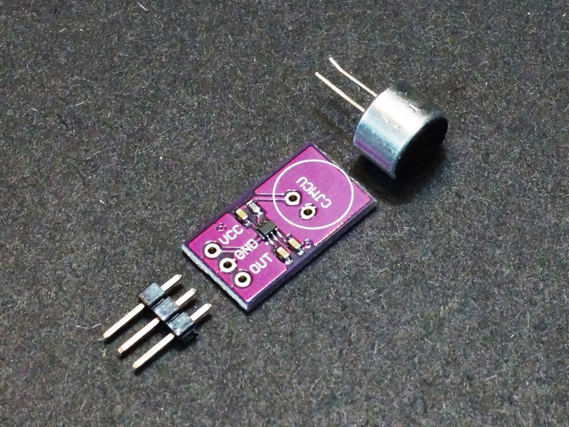
- MAX9812L Microphone Amplifier Board
- Microphone
- Male header strip
KEY FEATURES OF MAX9812L MICROPHONE AMPLIFIER MODULE:
- Small form factor
- 20dB fixed gain
- Very low 230uA quiescent current
- Rail-to-rail output
- 0.015% THD+N
- AC oupled output
- 3.3V operation
This is a basic microphone/amplifier combo board that provides a fixed 10x amplification of the signal. It can be used as a audio / voice input device or for general sound detection.
The Maxim MAX9812L chip the module uses is a tiny microphone amplifier designed for applications such as cell phones and laptops.
The module operates from 3.3V. This works well for use with a 5V Arduino or other uC that has a 3.3V output as this provides the cleanest power for the device.
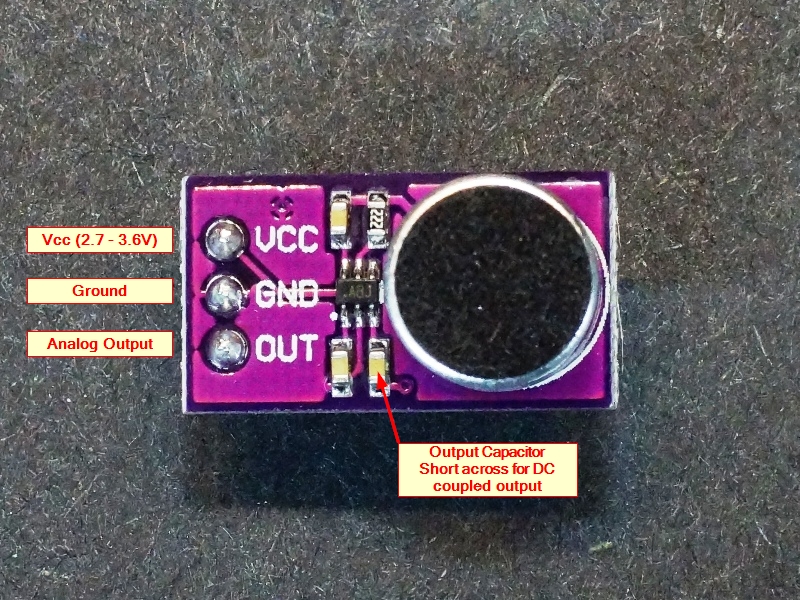
The output is an analog signal which is typically fed to the analog input on a uC. The output is AC coupled, but if it is desired to use it DC coupled, the output capacitor can just be shorted across. This capacitor is identified in the connections picture.
Since the module operates at 3.3V with a maximum output of 3.3V, it can be helpful to set the ADC reference voltage to 3.3V to provide finer resolution of the ADC readings. At 5V, the resolution is 5V/1024 = 4.88mV. With a reference voltage of 3.3V, the resolution is 3.3V/1024 = 3.22mV
Module Assembly
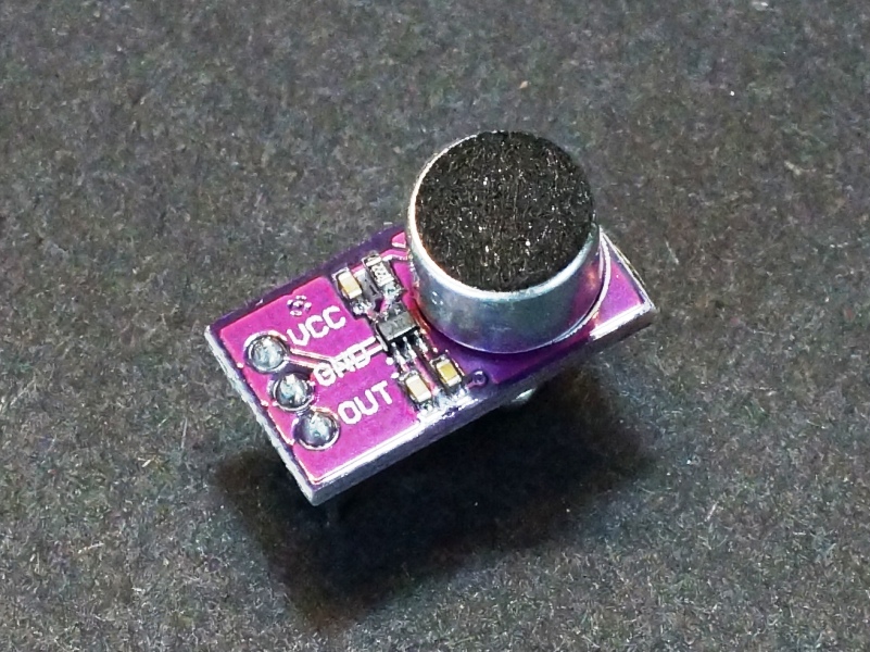
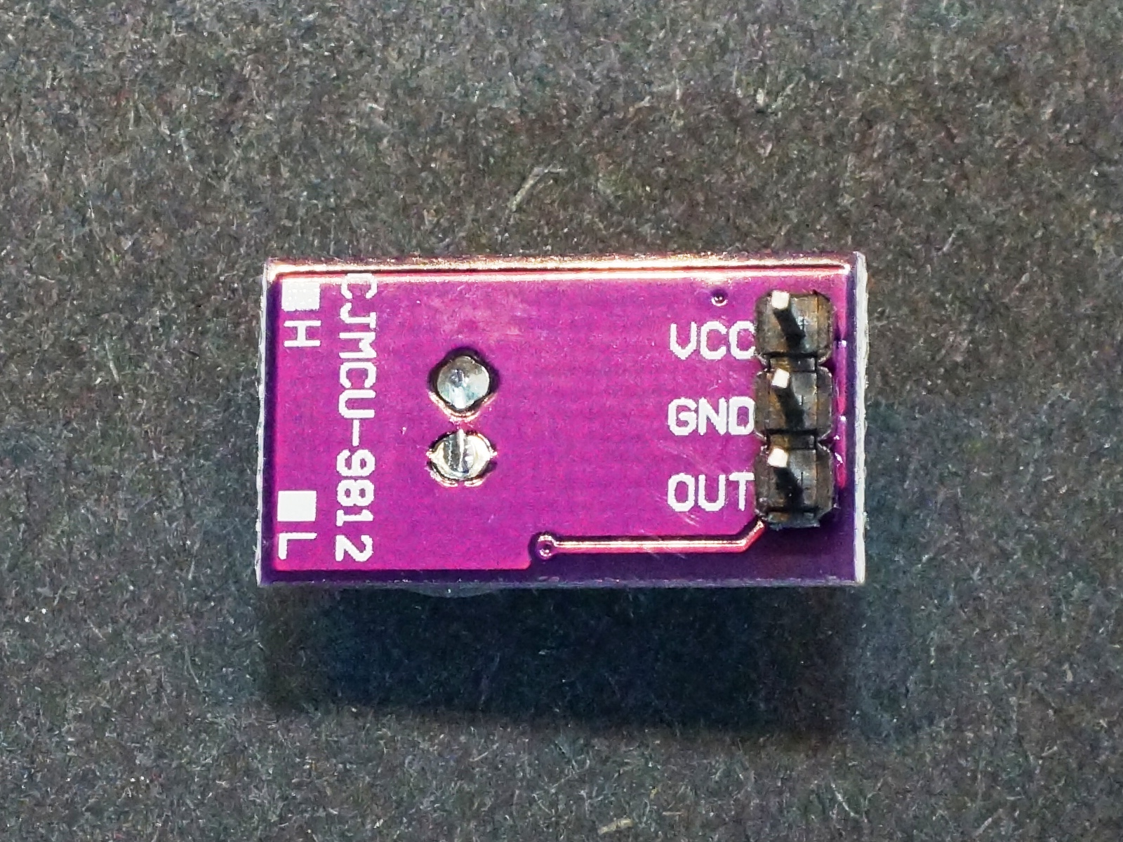
This module requires a small amount of soldering to complete the module by adding the microphone and the header. This allows you to configure the module to meet your particular requirements such as which side of the board you want the header on or if you want to solder on wires to make the connections. For use with breadboards, we put the headers on the bottom so that the module can plug directly into the breadboard.
When soldering, take note of the fact that the microphone has its leads offset to one side. When properly placed on the board, the body of the microphone should be centered in the silkscreen outline for it
Module Connections
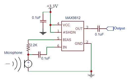
The connections to the module are simple. Just supply 3.3V power and ground and then run the analog output to where you need it.
1 x 3 Header
- VCC = VCC connects to 3.3V (2.7V – 3.6V)
- GND = Ground connects to uC ground
- OUT = Output typically connects to uC analog input or other analog input device
OUR EVALUATION RESULTS:
These are nice little modules that work as expected.
Below is a scope capture with a 300Hz tone being detected. Amplitude in this case is about 70mV, but will obviously vary depending on the sound volume.
Checking the Output
To get it up and running, simply hook the module up to 3.3V and ground and connect the Output pin to A0.
To see if the module is outputting something, you can run the program below which simply samples the A0 input every 10 milliseconds and sends it out the com port. In this program, we also set it to use an external AREF voltage for the ADC reference voltage, so you will need to jumper from the 3.3V to the AREF pin on the Arduino. Alternatively you can just remove this command from the program and it will use the default 5V reference voltage.
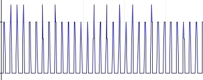
No DC Bias Applied
If the Serial Plotter window is then opened, the sample data will be shown in the plotter window.
With the same 300Hz tone as shown in the scope screen capture above, the plotted output looked like the image to the right.
It won’t be useful for much of anything, but at least you can tell that the module is basically working.
Providing DC Bias To Allow Capture Of Complete Output
Note that the bottom of the waveform is chopped off at the ADC value of zero. This is because the output of the module is AC coupled, so the output swings both positive and negative relative to ground and the analog input of the uC can’t capture any voltage below 0V so it is just chopped off.
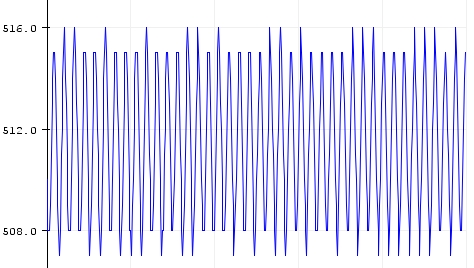
DC Bias Applied
In general, it is not good practice to input negative voltages into the analog (or any input) as it can potentially cause damage to the uC. The uC does have protection diodes on their inputs to help prevent damage, but they are limited in the amount of current that they can handle.
A better approach would be to make a simple voltage divider using two equal value resistors (like two 4.7K) between the Output of the module and one going to the VREF voltage and the other one going to ground.
This biases the output at 1/2 the VREF voltage which will be 2.5V if VREF is 5V or it will be 1.65V for a VREF of 3.3V.
This keeps the complete signal swing on the positive voltage side which the ADC input can handle. We now get an image that looks a little more like a sign wave, sorta, kinda.
The other option to bias the output is to short across the output capacitor on the module. This makes the module DC coupled to the ADC input which will have the same basic effect as did adding the voltage divider resistors.
MAX9812L Test Program
/*  MAX9812L Microphone Test Program
    Basic code to test the MAX9812L Microphone Amplifier Module
    Connect to 3.3V, Gnd and Signal goes to A0
    Optionally connect 3.3V to AREF input to use 3.3V for ADC operation
    Open Serial Plotter window to observe the audio waveform.
*/
int const MIC_PIN = A0;    // Mic output pin connected to A0
int Signal;                // Incoming ADC data. Value can range from 0-1024

//===============================================================================
//  Initialization
//===============================================================================
void setup() {
  analogReference(EXTERNAL);   // Set to use external ADC reference voltage.
                               // Connect 3.3V to AREF to provide reference voltage
  Serial.begin(9600);          // Set comm speed for serial plotter window
}

//===============================================================================
//  Main
//===============================================================================
void loop() {

  Signal = analogRead(MIC_PIN); // Read the sensor value
  Serial.println(Signal);                // Send the Signal value to Serial Plotter
  delay(10);
}
BEFORE THEY ARE SHIPPED, THESE MODULES ARE:
- Sample tested per incoming shipment
Notes:
- None
Technical Specifications
| Maximum Ratings | ||
| Vcc | 2.7 – 3.6V | |
| IMax | Maximum Current Draw | 400uA |
| Operational Ratings | Voltage Gain | 20dB (typ) |
| Power Supply Rejection Ratio | 100dB (typ) | |
| Bandwidth | 400kHz | |
| Dimensions | L x W (PCB) | 20 x 11mm (0.78 x 0.43″) |
| Country of Origin | China | |
| Datasheets | Maxim Microphone Amplifier | MAX9812L |

