


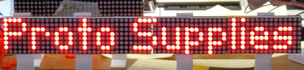
MAX7219 8×8 Dot Matrix (x4) Red Display Module
Original price was: $7.95.$6.95Current price is: $6.95.
Display has four 1.3″ 64 LED dot matrix displays with built-in MAX7219 serial LED drivers.
9 in stock
Description
The MAX7219 8×8 Dot Matrix Red Display Module has four 1.3″ 64 LED dot matrix displays with built-in MAX7219 serial LED drivers.
PACKAGE INCLUDES:
- MAX7219 8×8 Dot Matrix (x4) Red Display Module
- 8″ 5-wire F/F cable for hook-up or daisy-chaining multiple displays.
- 5-pin header which can be soldered to the module if daisy-chaining multiple modules together.
KEY FEATURES OF MAX7219 8×8 DOT MATRIX (x4) RED DISPLAY MODULE:
- Four 8×8 LED Matrix Displays with 1.3″ high red displays
- Built-in MAX7219 LED Drivers for each display
- SPI 3-wire serial interface for easy hookup to MCU
- Can daisy-chain multiple modules together for larger displays
MAX7219 LED Driver
The MAX7219 is a popular and flexible 7-segment, bar graph and dot matrix common cathode LED driver that supports many functions for controlling LED displays.
The driver provides flexible individual LED control as well as basic functions such as turning the display ON/OFF and adjusting the LED brightness.
The MAX7219 communicates with an MCU via a 3-wire SPI bus. Once the display is updated by the MCU, the MAX7219 then takes care of all the work of keeping the display refreshed, so it removes that overhead from the MCU which can be off doing other more important things.
SPI Interface
The module communicates via the SPI interface, so it only require 3 data pins to connect to a MCU.
If a larger display is needed, several modules can be daisy-chained together.
Libraries are readily available such as the “LedControl.h” library built-in to the IDE for Arduino that makes communicating with the display very straightforward.
Module Connections
There is an input header on one end and breakout locations on the other end for connecting additional modules.
Input Connector
The header pins on the left end is the main input connector. “Vcc” connects to 5V. Due to the fairly high current draw of the display (up to 1A if the brightness is cranked all the way up), it is recommended to drive it directly from a power supply rather than from the MCU power or else be sure to keep the brightness turned down to < 25% (level 3 of 15) to avoid overheating the MCU on-board voltage regulator or over-taxing the USB power. “GND” connects to ground which needs to be common with the MCU if an external power supply is used.
The other pins are for the SPI interface. “DIN” is the Data In. “CS” is Chip Select (sometimes labeled as LOAD) and “CLK is the Clock pin. These lasts 3 pins are connected to any digital outputs on the microcontroller. Which pins they connect to is defined when an instance of the LedControl is created as shown in the program below.
1 x 5 Header
- VCC – Connect to 5V. Connecting direct to power supply rather than from MCU is recommended.
- GND – Connect to system ground. This ground needs to be in common with the MCU
- DIN – Connect to any digital pin on MCU.
- CS / LOAD – Connect to any digital pin on MCU
- CLK – Connect to any digital pin on MCU.
Output Connector
The break-out pins on the other end of the assembly are used if it is desirable to daisy-chain displays. In this case, the “DOUT” is Data Out and it connects to the next modules “DIN” Data in pin. The other pins are passed straight-thru
1 x 5 Header
- VCC – Connect to 5V on next module if looping power through.
- GND – Connect to GND on next module
- DOUT – Connect to DIN on next module.
- CS / LOAD – Connect to CS / LOAD on next module
- CLK – Connect to CLK on next module
The module ships with the output header loose. This allows you to solder them on the top or bottom of the board or use wires depending on how you want to use the module.
OUR EVALUATION RESULTS:
These are useful modules and fun to play with. The large number of LEDs allows for alphanumeric display or pretty much anything else that you can think of. You can get creative and stack them and make a Tetris game or something. The main limitation on these displays is just in the creativity of the programming.
The displays are socketed as shown in one of the pictures. If the display doesn’t seem to be working right, make sure that the modules are firmly seated in the sockets. If they are removed for some reason, be sure to reinstall in the same orientation with the printed side of the module on the side nearest the VCC pin as shown in one of the pics. Also ensure no pins are accidentally bent over.
The software below uses the “LedControl.h” library to implement basic functionality of the module.
The display is wired to digital pins 12,11 and 10 for DIN/CLK/CS, but these can be any 3 digital pins. Just redefine the pins used in the statement
LedControl lc=LedControl(12,11,10,displayCnt);
The intensity is set to 3 (out of 15) to help keep the maximum current draw when all LEDs are on within the limits of the on-board regulator if external DC power is used or within the limits of the USB connection if power is supplied via USB.
If you have a problem with the display not displaying correctly after power is first applied, try resetting the processor. In some cases, the initial power on surge if all LEDs happen to come on at full brightness for a moment when power is first applied before the program starts running can cause a software glitch.
MAX7219 8×8 Dot Matrix x 4 Display Module Example Program
/*
 * MAX7219 based Dot Matrix Test
 *
 * Initialize the display, then run through some low level primitives
 * to move a dot across the display and then columns and rows.
 * Uses libraries LedControl.h and binary.h
 */
#include "LedControl.h"
#include "binary.h"

int displayCnt = 4;  // # of displays connected (between 1-8)
int intensity = 3;   // Brightness of displays (between 0-15)
int idx = 0;         // Index for loops

// Create instance of LedControl called 'lc'
LedControl lc=LedControl(12,11,10,displayCnt);  // Pins: DIN,CLK,CS, # of Displays
//===============================================================================
//  Initialization
//===============================================================================
void setup()
{

  for(idx=0; idx<displayCnt;idx++) {
    lc.shutdown(idx,false);  // Wake up displays
  }
  for(idx=0; idx<displayCnt;idx++) {
    lc.setIntensity(idx,intensity);  // Set intensity levels
  }
  for(idx=0; idx<displayCnt;idx++) {
    lc.clearDisplay(idx);  // Clear Displays
  }
}
//===============================================================================
//  Main
//===============================================================================
void loop()
{
  // Move a dot across the display
  for (int display = 0; display <= displayCnt ; display++) {
    for (int col = 7; col >= 0; col--)  {
      for (int row = 0; row <= 7; row++)  {
        lc.setLed(display,row,col,true);
        delay (60);
        lc.setLed(display,row,col,false);
      }
    }
  }
  // Draw rows down the display
   for (int row = 0; row <= 7; row++)  {
     for (int display = 0; display < displayCnt; display++) {
     lc.setRow(display, row, B11111111);
     }
     delay(750);
    }
  for(idx=0; idx<displayCnt;idx++) {
    lc.clearDisplay(idx);  // Clear Displays
  }
  // Draw columns across the displays
   for (int col = 0; col <= 7; col++)  {
     for (int display = 0; display < displayCnt; display++) {
     lc.setColumn(display, col, B11111111);
     }
     delay(750);
    }
   // Clear displays one dot at a time
   for (int display = displayCnt; display >= 0; display--) {
    for (int col = 7; col >= 0; col--)  {
      for (int row = 0; row <= 7; row++)  {
        lc.setLed(display,row,col,false);
        delay (60);
      }
    }
  }
}
BEFORE THEY ARE SHIPPED, THESE MODULES ARE:
- Sample inspected and tested per incoming shipment.
Notes:
- The back of the board has exposed pins, so some care should be used to avoid possible shorting if placed on a metallic surface.
Technical Specifications
| Display | Configuration | 8 x 8 Dot Matrix (x 4 displays) |
| Color | Red | |
| Operating Ratings | DC Power Input | 5V |
| I(typ) No LEDs lit | 30mA | |
| I(typ) All LEDs lit, Min Brightness | 140mA | |
| I(typ) All LEDs lit, Max Brightness | 1000mA | |
| Dimensions | Display Size | 130 x 32 mm (5.1 x 1.3″) |
| Display Height w/ PCB | 14mm (0.55″) (typical) | |
| Character Size | 32 x 32 mm (1.26″) | |
| Datasheet | MAX7219 |