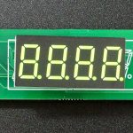
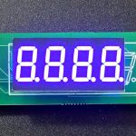
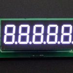
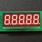
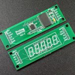
MAX7219 0.36″ 3 to 5-Digit 7-Segment Remote Adapter
$0.79
Small adapter for space constrained applications
64 in stock
Description
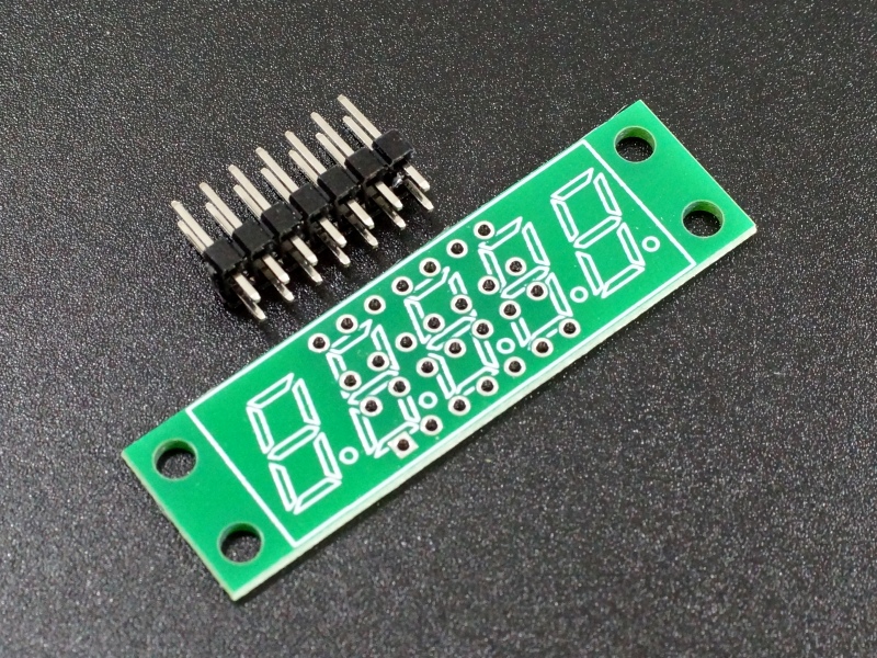
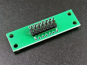
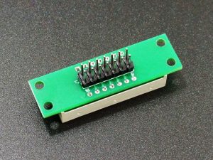
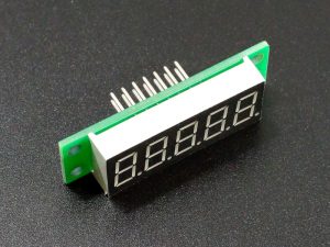
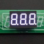
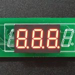
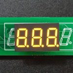
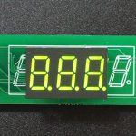
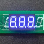
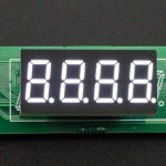
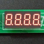
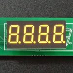
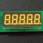
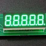
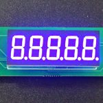
This adapter board mounts a 3, 4 or 5 digit 0.36″ 7-segment display on the front side and a 2×7 male header on the back side that brings out the display pins.
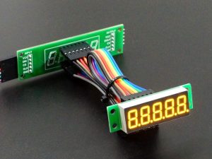
This allows it to be remotely attached to our MAX7219 0.36” 7-segment display board or similar device via cables to drive the display. This mainly comes in handy when working with tight space constraints for mounting the display.
PACKAGE INCLUDES:
- Qty 1 – MAX7219 0.36″ 3 to 5-Digit 7-Segment Remote Adapter
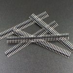
- Qty 1 – 2×7 Male Straight Header
KEY FEATURES OF MAX7219 0.36″ 3 TO 5-DIGIT 7-SEGMENT REMOTE ADAPTER:
- Mounts a 0.36″ Common Cathode 12 or 14-pin 7-segment LED display module
- Mounts header for wiring to a remote mounted driver board.
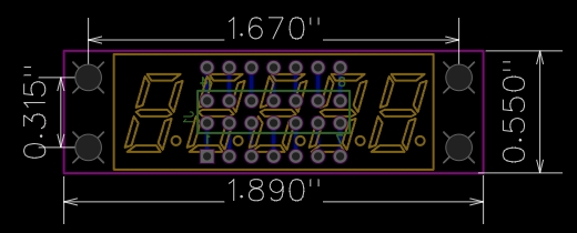
- 48 x 14mm (1.89 x .55″)
It is optimized to mount a 5-segment display with small mounting ears on either side but can also be used with 3 and 4 digit displays. The PCB can be trimmed in length if needed to remove the mounting ears or to fit smaller displays with minimal footprint down to just the outline of the LED display itself.
Assembly
Assembly is fairly simple with just a little easy thru-hole soldering required.
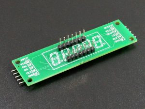
First mount and solder the male header. It goes on the side with the outline for J1.
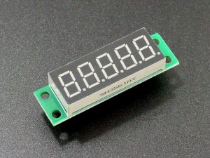
Next install the LED module. It goes on the side with the LED silkscreen. A 14-pin module will fill all the holes. A 12 pin module will be justified to the end with the J1 silkscreen i.e. pin 1 of the board will line up with pin 1 of the module.
The module has built-in corner standoffs that provide enough clearance for the male header pins that protrude through the board. Ensure that the decimal points on the display match up with the silkscreen. Since the board is fully symmetrical, if installed upside down, the board can just be rotated 180° and it will work fine.
Once complete, it should look something like this.
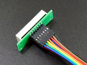
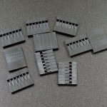
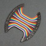
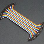
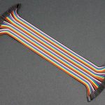
Standard female-to-female Dupont style breadboard jumpers can be used with 7-pin connector housings to easily make jumper cables in 4”, 8” or 12” lengths with no crimping required. Just peel two 7-conductor sections off the cable, remove the single connector housings and reinsert the pins into the 7-pin housings.
To connect to a driver board like our MAX7219 0.36″ 3 to 5-digit 7-segment display board, it will need to have two 1×7 male headers soldered on where the display would normally go for connecting to cables.
Module Connections
There a 2×7-pin header on the assembly. The LED pins are brought straight out to the header, so cabling is simply 1 to 1 with the display driver board.
Installation
The boards have four M3 (0.118″) size mounting holes in the corners on 1.67 x 0.315″ centers. Since there are no traces in the area, these mounting ears can be scribed and broken off or cut off if needed to further minimize the space the display occupies.
Board drawings can be found at the bottom of the page.
User Added Parts to Configure the Modules
The items in this section can be added to the order if they are needed to finish the configuration of your displays. Click on pics for more info about each item.
To avoid overpowering the camera, the pictures are taken with the LEDs turned down as far as they will go. Brightness and color saturation is not an issue with these displays.
3-Digit 0.36″ CC LED Modules:
4-Digit 0.36″ CC LED Modules:
5-Digit 0.36″ CC LED Modules:
Misc Hardware:
Notes:
- None
Technical Specifications
| Display Type Mounted | 0.36″ 78-Segment | 3, 4 or 5 digits, Common Cathode, 12/14-pin |
| Dimensions | ||
| PCB (L x W) | 48 x 14mm (1.89 x .55″) | |
| Mounting holes (L x W) | 42.4 x 8mm (1.67 x 0.315″) | |
| Mounting hole size | 3mm (0.118″) | |
| Country of Origin | Designed in USA | Manufactured in China |

