Magic Light Cup Module(2-Pack)
$1.50
Modules incorporate both a mercury tilt switch and LED on the same module for making special effects.
Out of stock
Description
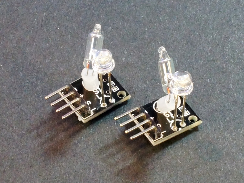
The Magic Light Cup Module incorporates both a mercury tilt switch and LED on the same module for making special effects by handling them.
PACKAGE INCLUDES:
- Magic Light Cup Module
KEY FEATURES OF MAGIC LIGHT CUP MODULE:
- Glass mercury tilt switch
- Independent red LED
- Mainly for creating a special effect as shown below

This module incorporates a mercury tilt switch and LED in the same module but they are independently controlled.
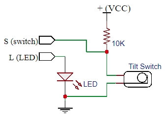
The mercury tilt switch includes a small amount of conductive liquid mercury in a glass housing. The ball of mercury rolls and makes or breaks contact with switch electrodes as the module is tilted. The tilt switch output is brought out to a pin on the module.
The tilt switch has a 10K pull-up resistor which keeps the output high until the mercury grounds the connection. Vcc is connected to this module just for this pull-up. If the internal pull-up on the uC is enabled, the Vcc line does not need to be connected.
The LED on the module is separately controllable via an input pin on the module. The LED is lit with a logic HIGH input. It requires a series current limiting resistor of approximately 120 ohms or larger to prevent possible damage to the LED or the uC driving it.
Module Connections
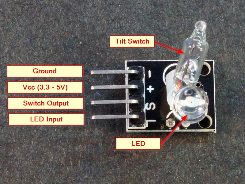
There is a 4-pin header on the assembly for making connections.
1 x 3 Header
- ‘G’ / ‘–’ = Ground
- ‘+’ = Vcc (3.3 or 5V to match uC)
- S = Output of the tilt switch. Connects to digital input pin on uC. Active LOW
- L = Input to drive LED. Connects to digital output pin on uC. Active HIGH
OUR EVALUATION RESULTS:
This module can be used to detect a tilt condition using a microcontroller which can then light the LED if a tilt is detected, but that frankly gets boring pretty quickly.
We sell these as a 2-pack so that the modules can interact with each other which is a little more interesting. The snazzy name ‘Magic Light Cup‘ refers to having two of these modules hooked up and as the modules are tilted like pouring one into the other, the light will appear to pour from one of the modules to the other.
The program below monitors the tilt switch states and uses PWM to dim or brighten the LEDs depending on how the modules are handled. The logic can be modified to change the behavior.
Magic Light Cup Example Program
/*
Magic Light Cup Module Example
Make connections using M/F jumper wires so that you can move the modules
and pour the light from one module to the other.
*/

int LedPinA = 5;      // Any PWM Output Pin to drive LED on Module A
int LedPinB = 6;      // Any PWM Output Pin to drive LED on Module B
int switchPinA = 7;   // Any Digital Input Pin to monitor tilt sensor on Module A
int switchPinB = 4;   // Any Digital Input Pin to monitor tilt sensor on Module B
int switchStateA = 0; // Current switch State on Module A
int switchStateB = 0; // Current switch State on Module B
int brightness = 0;   // Variable to ramp brightness up or down using PWM
//===============================================================================
//  Initialization
//===============================================================================
void setup()
{
  pinMode(LedPinA, OUTPUT);
  pinMode(LedPinB, OUTPUT);
  pinMode(switchPinA, INPUT);
  pinMode(switchPinB, INPUT);
}
//===============================================================================
//  Main
//===============================================================================
void loop()
{
  switchStateA = digitalRead(switchPinA);         // Check the tilt sensor on Module A
   if (switchStateA == HIGH && brightness != 255) // If switch high, increase brightness
   {
   brightness ++;
   }
   switchStateB = digitalRead(switchPinB);        // Check the tilt sensor on Module B
   if (switchStateB == HIGH && brightness != 0)   // If switch is high, decrease brightness
   {
   brightness --;
   }
   analogWrite(LedPinA, brightness);              // Set the PWM brightness of Module A
   analogWrite(LedPinB, 255 - brightness);        // Set the PWM brightness of Module B
   delay(25);
}
BEFORE THEY ARE SHIPPED, THESE MODULES ARE:
- Inspected
- Basic operation verified
- Packaged in a resealable ESD bag for protection and easy storage.
Notes:
- This is similar to or the same as the KY-27 module.
Technical Specifications
| Operating Ratings | Vcc Range | 3.3 – 5V |
| Logic high | Pulled to Vcc | |
| Logic Low | Pulled to Ground | |
| Dimensions | L x W (PCB) | 19 x 16mm (0.75 x 0.6″) |


