LTC1871 Adjustable DC-DC Boost Module
$10.95
Boosts a 3.5 – 30V input up to 3.5 – 30V output @ up to 10A and a maximum of 100W
5 in stock
Description
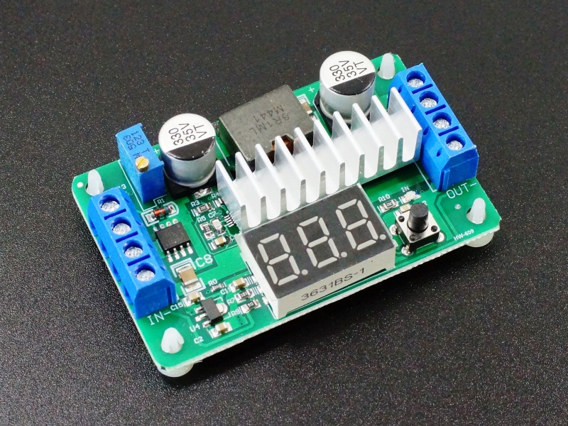
The LTC1871 Adjustable DC-DC Boost Module can step-up input voltage to a range of 3.5 – 30V at up to 10A.
PACKAGE INCLUDES:
- LTC1871 Adjustable DC-DC Boost Module
KEY FEATURES OF LTC1871 ADJUSTABLE DC-DC BOOST MODULE:
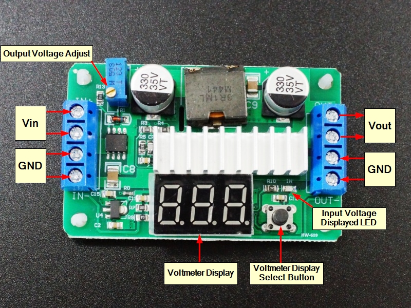
- Built-in input/output voltage display
- LT1871 step-up converter IC
- MOSFET/Rectifier heatsink
- Output voltage adjustment
- Output current up to 10A (see chart below)
- Input voltage range 3.5 to 30V
- Output voltage range 3.5 to 30V
DC-DC Boost converters step up the input voltage to a higher voltage while also stepping down the available current since the module can’t output more power than it inputs.
This LTC1871 based DC-DC Boost Converter is adjustable and capable of outputting a voltage range of 3.5 – 30V at a continuous current of up to 6A and short-term current of up to 10A. Maximum power output is up to 100W depending on the operating voltages.
The input is range is also 3.5 – 30V and the input must be less than or equal to the output setting.
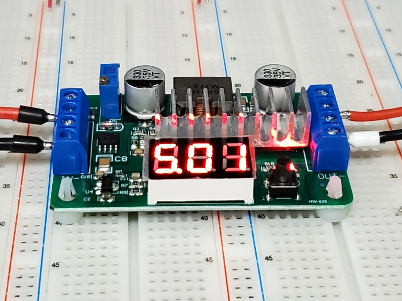
The module has a red built-in voltmeter that shows the the Input and output voltage.
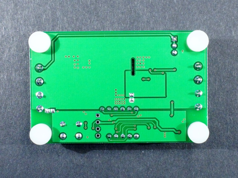
The module comes with 4 plastic feet installed in the 4 corner mounting holes which work well for using the module on the prototype bench. These can be removed and the holes used for screws if it is desired to permanently mount the module.
Input / Output Display
The module has a built-in red voltmeter that has a stated 0.1 digit accuracy.
A single button toggles the display between showing the input voltage, the output voltage or automatically switching between showing the input and output voltages every 3 seconds. When the Input voltage is being displayed, a red LED lights so you know which voltage is being displayed.
In addition, if the button is pressed and held for about 3 seconds it will show the current display mode.
Display shows ‘[0]‘ = input voltage is being shown
Display shows ‘[1]‘ = output voltage is being shown
Display shows ‘[2]‘ = It is automatically switching between the input and output voltage every 3 seconds.
If the button is then held down for approximately 2 additional seconds the display will then switch off. Another press of the button will cause the display to come back on.
Voltage Adjustment
The module has a multi-turn potentiometer for adjustment of the output voltage. Turning the pot CW increases the output voltage while turning it CCW decreases the output voltage.
The lowest possible voltage will be determined by the input voltage. The highest voltage generally tops out a little over 30V.
Module Connections
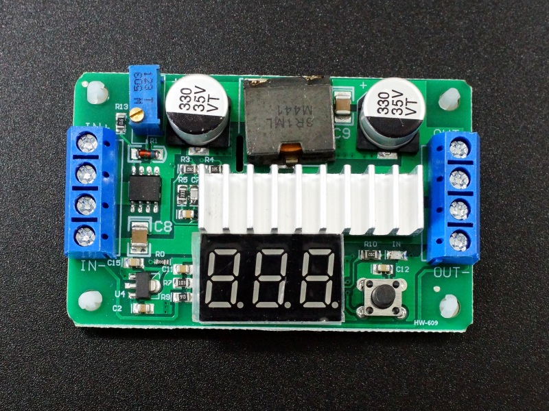
These are compact boards with the input on the left end of the board and the output on the right. The input and output connectors are screw terminal type with 2 connection points for each voltage and ground point which can be handy if you are hooking up more than one load or want to run redundant smaller wires.
Input Power (2 terminals for each connection)
- IN+ = Input voltage (3.5 – 30V)
- IN- = Ground
Output Power (2 terminals for each connection)
- OUT+ = Output voltage (3.5 – 30V)
- OUT- = Ground
Note: The input and output ground are connected together on the module.
OUR EVALUATION RESULTS:
The board is generally well built with appropriately sized components to handle the specified power and fairly good efficiency for these types of modules.
The DVM display has good accuracy of the input voltage of ±1 digit. The output voltage reading tends to change with the load put on the module even though the output voltage doesn’t change. A 12V output at idle may read 12.3V at high load. If absolute accuracy is required, a separate DVM should be used to measure the output during adjustment.
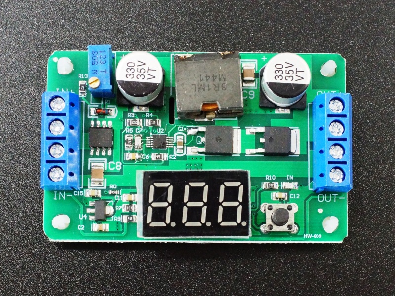
The power MOSFET and Schottky diode have a heat sink applied. In some units, there may also be a heatsink on the inductor which is reasonably sized and has a saturation current of 16A. The power N-Channel MOSFET does most of the heavy lifting of power switching in this design and the actual LTC1871 converter IC dissipates relatively little power.
The LTC1871 converter IC has a programmable operating frequency range of 50kHz to 1MHz and it measured running at about 500KHz. The IC also has a built-in over-voltage shutdown.
The table below gives some thermal results with an ambient temperature of approx 22°C and no fan cooling. We tested at approximately 6A input or the max supported by the module. Our bench supply is limited to a max of 6.4A output. The MOSFET temp is measured with the heat sink removed for access. As with most of these types of heat sink setups, when the component tab is soldered to the PCB, adding a heat sink to the plastic body of the component generally has a relatively minor effect on the cooling of the part though it does help especially if there is air movement.
Output Current vs Input / Output Voltage
| Voltage In | Voltage Out | Amps Out | Watts Out | Amps In | Watts In | Efficiency | MOSFET Temp °C |
| 5 | 9 | 3.0 | 27 | 6.38 | 31.8 | 85% | 75 |
| 12 | 2.28 | 27.3 | 6.36 | 31.8 | 86% | 70 | |
| 24 | 1.18 | 28.2 | 6.3 | 31.5 | 90% | 67 | |
| 9 | 12 | 4.35 | 56.9 | 6.32 | 56.9 | 92% | 86 |
| 24 | 2.21 | 53 | 6.38 | 57.42 | 92% | 78 | |
| 30 | 1.75 | 52.5 | 6.38 | 57.24 | 92% | 79 | |
| 12 | 24 | 3.01 | 72.3 | 6.38 | 76.56 | 94% | 85 |
| 30 | 2.38 | 71.4 | 6.38 | 76.56 | 93% | 91+ | |
| 24 | 30 | 3.8 | 114 | 4.86 | 116.64 | 98% | 89 |
Output ripple runs between 50-250mV for most input/output settings. There is a fair amount of high frequency switching noise on the output which increases with increased loading that can reach a volt or more.
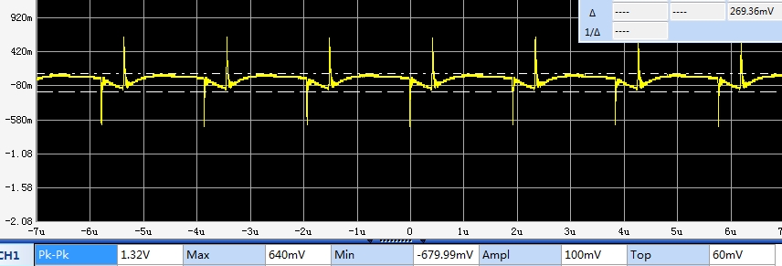
LTC1871 Ripple and Noise
BEFORE THEY ARE SHIPPED, THESE MODULES ARE:
- Inspected
- Output is set for 12V
- Load tested 5V @ 5A in, 12V out
- Packaged in a high quality resealable ESD bag for protection and easy storage.
FURTHER READING
For more info on DC-DC Converters in general, see our DC-DC Converter Overview page.
Notes:
- Be sure to properly hook up the input and output connections before applying power to avoid possible damage to the module.
Technical Specifications
| Maximum Ratings | ||
| VIN | Maximum Input Voltage | 30V |
| IO | Maximum Output Current | 10A |
| Operating Ratings | ||
| VO | Output Voltage Range | 3.5 – 30V |
| IO | Output Current (max continuous) | 6A |
| Switching Frequency | 50kHz-1MHz (500kHz measured) | |
| Output Ripple | Varies depending on load | 50-250mV |
| Efficiency | Varies depending on load | 85%-98% (measured) |
| Electrical Isolation | Non-isolated | |
| Dimensions | L x W x H | 67mm x 42mm x 20mm (2.6″ x 1.7″ x 0.8″) |
| Datasheet | LTC1871 IC |

