LM393 Dual Voltage Comparator
$0.59
Two independent voltage comparators operate from a single or split supply.
74 in stock
Description
The LM393 Dual Voltage Comparator contains two independent precision voltage comparators designed to operate from a single or split supply.
PACKAGE INCLUDES:
- LM393 Dual Voltage Comparator
KEY FEATURES OF LM393 DUAL VOLTAGE COMPARATOR:
- Low input offset voltage of 5.0 mV
- Low operating current of 0.4 mA
- Operates from a single positive power supply of 2 to 36V
- Can also operate from a split supply of ± 1.0 to ±18V
The LM393 contains two differential comparators that are completely independent other than they share a common power supply connection. It can operate on a wide single supply range of 2 to 36V or split supply range of +/- 1 to 18V
As the name implies, voltage comparators are used to compare one voltage to another and output either a logic HIGH or LOW level based on the results of that comparison.
The most common use for these parts is to monitor an analog signal to see if it goes beyond a threshold that requires some action to be taken.
These parts are very commonly used on modules that provide an adjustment potentiometer to set when we want an output to trip HIGH or LOW based on some threshold being reached, usually from an analog sensor such as for temperature, light or sound. In this case, the pot is setting a reference voltage on the comparator which is compared to the output voltage of the sensor.
When monitoring an analog sensor, one option is to bring that analog sensor signal directly into an analog port on a uC and continually monitor it in the software. Using a comparator on the other hand allows this monitoring to be done external to the uC and the digital output of the comparator can be brought into a digital pin that can be monitored more simply, similar to how a switch would be monitored for being either ON or OFF. The output can also be brought in on an interrupt pin so that no monitoring is required and the uC only takes an action when the comparator tells it to. In many cases, using a comparator can remove the need for having a uC at all and the output can be used to directly drive a device such as a relay to take some action or LED to indicate some condition has been reached.
Theory of Operation
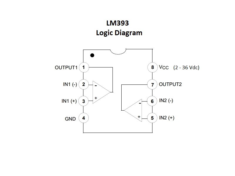
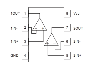
Each of the comparators in the LM393 have two inputs marked ‘+’ and ‘-‘. The device simply compares the difference in voltage between these two input pins and sets the digital output accordingly.
- If the ‘+’ input voltage is higher than the ‘-‘ voltage, the output goes HIGH.
- If the ‘-‘ input voltage is higher than the ‘+’ voltage, the output goes LOW
If you will be using the device with a uC, you should power the LM393 off the same voltage that the uC is running at so that the output is logic compatible with the uC.
The output is open collector which means that the LM393 will pull it to ground when it outputs a logic LOW, but when the output goes HIGH, an external pull-up resistor is needed to pull it HIGH. In most applications, a pull-up resistor will be required on the output. Most uC have the option to enable pull-up resistors on their digital inputs and so a physical resistor is generally not required.
Night Light Example Circuit
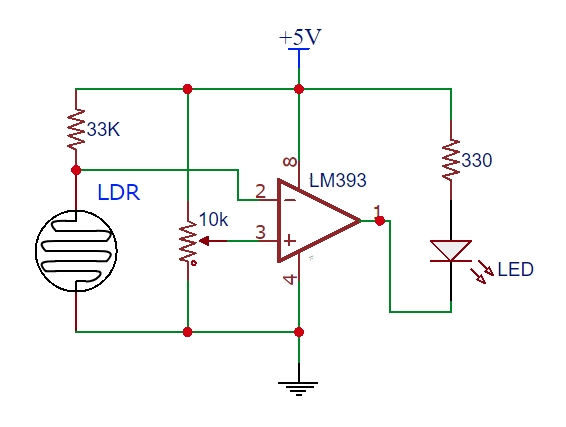
The circuit shown here implements a simple night light using one of the comparators.
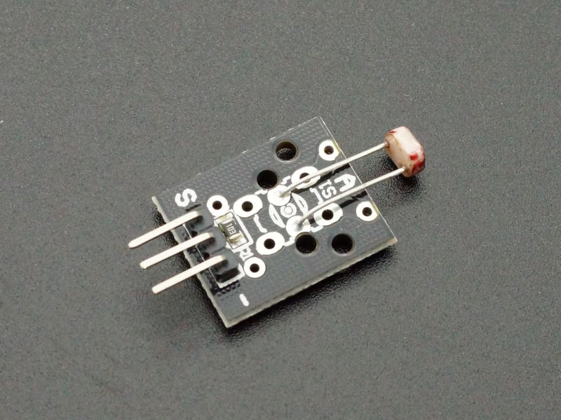
The LDR (Light Dependent Resistor) changes resistance with the amount of light falling on it. As the amount of light increases, the resistance goes down. Conversely, when the light intensity decreases the resistance goes up.
The LDR is in series with a 33K resistor forming a voltage divider. The 33K value is not overly critical. With strong lighting, the low resistance of the LDR will keep the voltage on the ‘-‘ pin low. As the light decreases and the resistance goes up, the voltage will start to rise toward 5V and once it exceeds the voltage on the ‘+’ pin, the output will go LOW, thus turning on the LED night light.
The potentiometer can be used to adjust the voltage on the ‘+’ pin and therefore set the trip-point for when the comparator switches state.
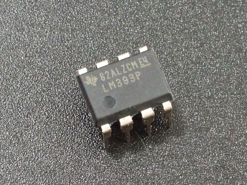
The part comes in a DIP-8 package and is breadboard friendly.
Notes:
- None
Technical Specifications
| Operational Ratings | V+ | 2 – 36V |
| V+ / V- | ±1.0V to ± 18V | |
| Typical Sink Current | 16mA | |
| Package | DIP-8 | |
| Package Type | Plastic, thru-hole | |
| Mfr | Onsemi or TI | |
| Datasheet | LM393 |

