LM386 Audio Amplifier
$0.39
General purpose single-channel audio amplifier that can handle up to 700mW
59 in stock
Description
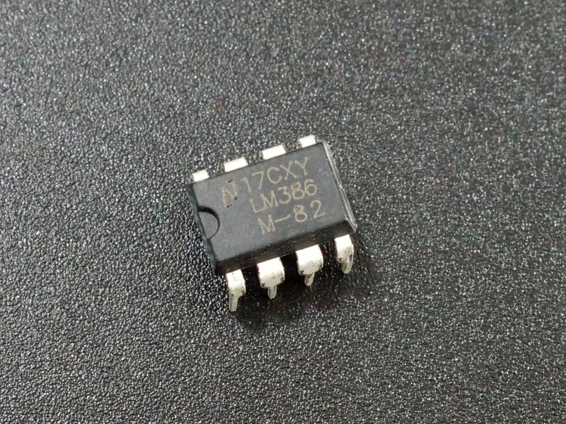
The LM386 Audio Ampifier is a general purpose single-channel audio amplifier that can handle up to 700mW and is easy to use.
PACKAGE INCLUDES:
- LM386 Audio Amplifier
KEY FEATURES OF LM386 AUDIO AMPLIFIER:
- 20x fixed gain adjustable up to 200x
- 700mW power
- 5-12V operation
- Easy to use and inexpensive
The LM386 are handy for providing basic audio amplification in a project such as if you want to drive a speaker off a PWM pin on a uC and want more oomph than the uC can provide directly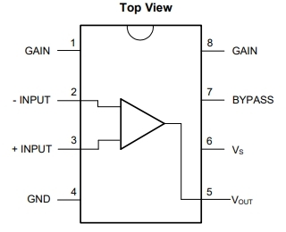
These parts are LM386N-1 or equivalent parts. They operate at 5V – 12V and provide up to 700mW of power. The higher the operating voltage, the higher the maximum amount of power that it can provide. The output can drive loads from 4 to 32 ohms. The lower the resistance of the load, the more power it can provide, so a 4 ohm speaker will be about twice as loud as an 8 ohm speaker.
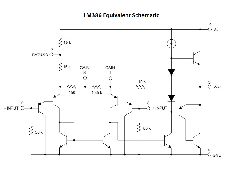
The gain is fixed at 20x when using a minimal parts count setup, but volume can be adjusted using a pot on the input. If a greater gain is desired, a capacitor and resistor can be added between pins 1 & 8 to program the gain up to a max of 200x.
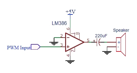
Minimal Parts Count LM386 Example Circuit
Below is a minimal parts setup to drive a speaker off a PWM pin from a microcontroller. The output capacitor between the amplifier and speaker is needed to avoid overheating the LM386 or damaging the speaker. Value is not critical, but should be in the range of a 220-470uF or so. Since the max input signal on the LM386 is 0.4V, the 5V PWM input will be clipped.
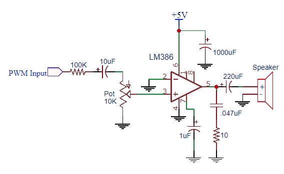
More Full Feature LM386 Example Circuit
For a more functional setup that adds additional capability, checkout to the circuit below. It adds the following:
- Potentiometer on input to provide volume control.
- Series 100K resistor drops the 5V PWM voltage down so it is within the LM386 input spec. Not needed when working with small signal inputs.
- A series 10uF input capacitor removes any DC offset that may be on the input signal.
- A small 10 ohm resistor / .047uF cap pair are added to the output to provide stability at high frequencies by providing a load for the amplifier at higher frequencies than the speaker can handle.
- A small tantalum or electrolytic cap of 1uF-4.7uF is added to the pin 7 to provide some bypass filtering on the input circuit. A more readily available 0.1uF cap will also work fine in many applications.
- A 1000uF or similar large electrolytic filter cap is added across power and ground to primarily avoid 60hz noise coupling into the amplifier that can create hum.
- You will often see a 10uF cap or cap/resistor pair connected between pins 1 & 8 to increase the gain of the amplifier. In breadboard setups, this can sometimes create too much feedback and so I have left it out to minimize the chance of having issues. If you are trying to boost a very low signal like a condensor mic output, you may want the extra gain. A 10uF cap across these pins (positive lead goes to pin 1) with no series resistor will give the max gain of 200x.
When using a solderless breadboard, be sure to keep wires and leads short to minimize noise pickup.
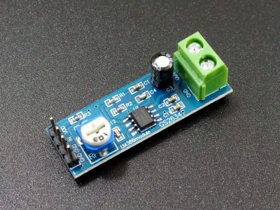
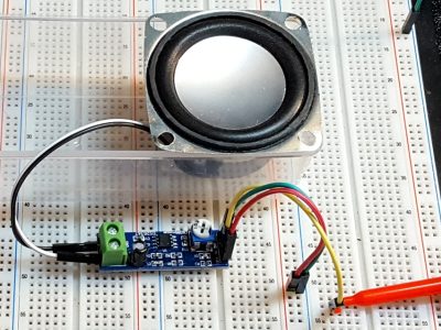
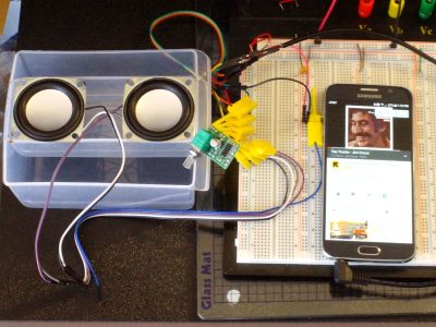
If you are looking for a prebuilt or more capable audio amplifier solution, take a look at our LM386 Audio Amp Module or PAM8403 Stereo Module down below.
Notes:
- None
Technical Specifications
| Operational Ratings | ||
| Vs | Vcc Power Range | 4-12V |
| Vi | Voltage on input pins | -0.4 to 0.4V |
| Pmax | Maximum output power | 700mW (typ) |
| Load | 4 Ohm – 32 Ohm | |
| Package | DIP-8 | |
| Package Type | Plastic, thru-hole | |
| Mfr | Various | |
| Datasheet | LM386 |

