LM317 Adjustable Linear Regulator Module
$1.95
Regulates 4.5 – 40V input to a 1.25 – 37V output @ up to 1.5A
37 in stock
Description
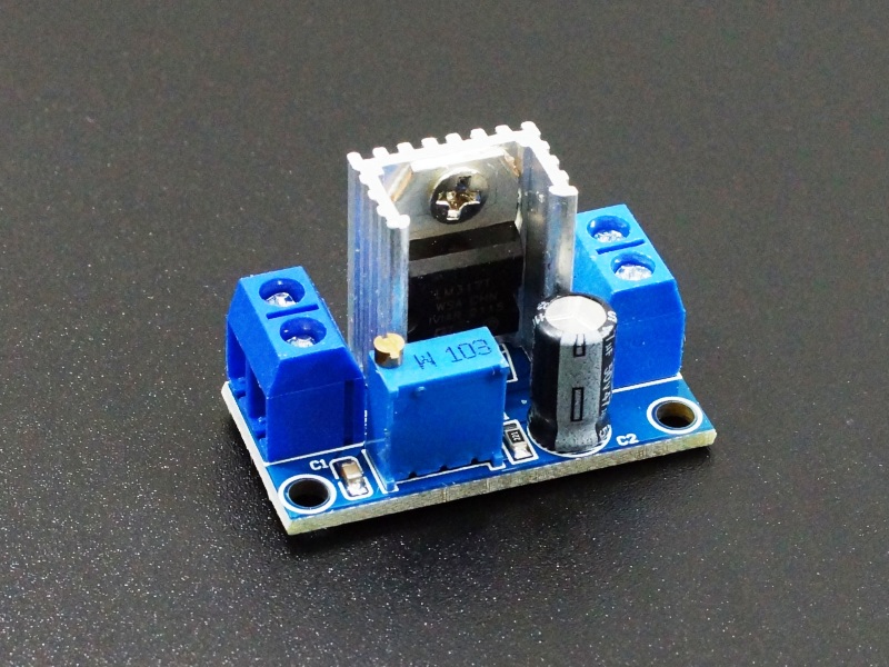
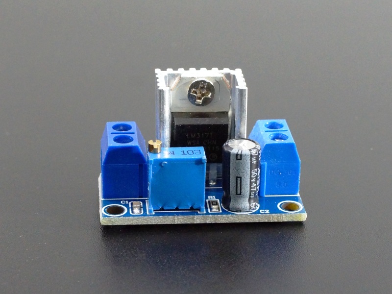
The LM317 Adjustable Linear Regulator Module can output 1.25 – 37VDC at up to 1.5A.
PACKAGE INCLUDES:
- LM317 Adjustable Linear Regulator Module
KEY FEATURES OF LM317 ADJUSTABLE LINEAR REGULATOR MODULE:
- Compact size
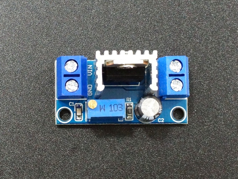
- LM317 linear regulator IC with heatsink
- Output voltage adjustment
- Output current up to 1.5A (see chart below)
- Input voltage range 4.5 to 40V
- Output voltage range 1.25 to 37V
Linear regulators have less ripple on their outputs compared to DC-DC converters that can be used for the same purpose, but the trade-off is that the linear regulators also tend to dissipate more heat in the process and so are less efficient than a comparable DC-DC converter. Linear regulators are best used when the input to output voltage can be kept to a minimum.
The LM317 is perhaps the most commonly used adjustable linear regulator of all time. It is similar to the ubiquitous 7805 fixed 5V regulator but with an adjustable output that can range from 1.25-37VDC at up to 1.5A.
The LM317 has built-in current limiting and thermal protection features which makes it fairly robust.
The board has 2 holes which can be used for mounting it permanently if desired using two small M3 screws.
Voltage Adjustment
The on-board multi-turn potentiometer allows for adjustment of the output voltage.
Turning the pot CW decreases the output voltage while turning it CCW increases it.
The available adjustment range will depend on the input voltage. The LM317 has a voltage drop of approximately 1.25V, so the typical range is from a minimum of 1.25V up to the input voltage – 1.25V. If powering the module with 12V for instance, the output range would be approximately 1.25V to 10.75V.
Module Connections
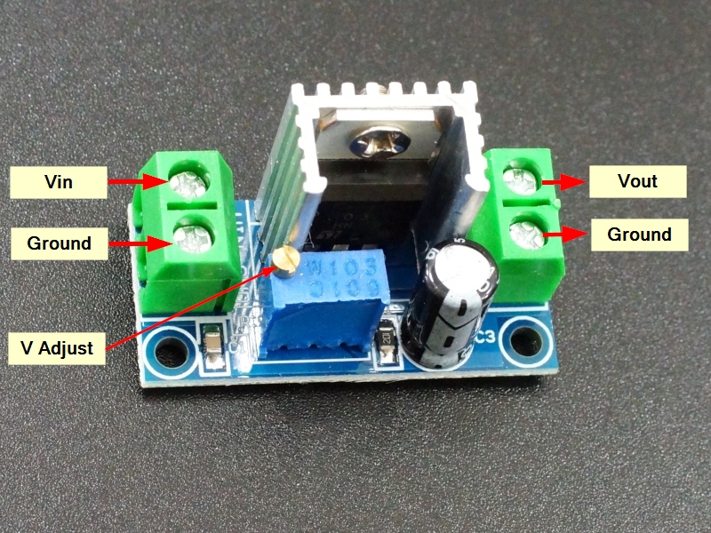
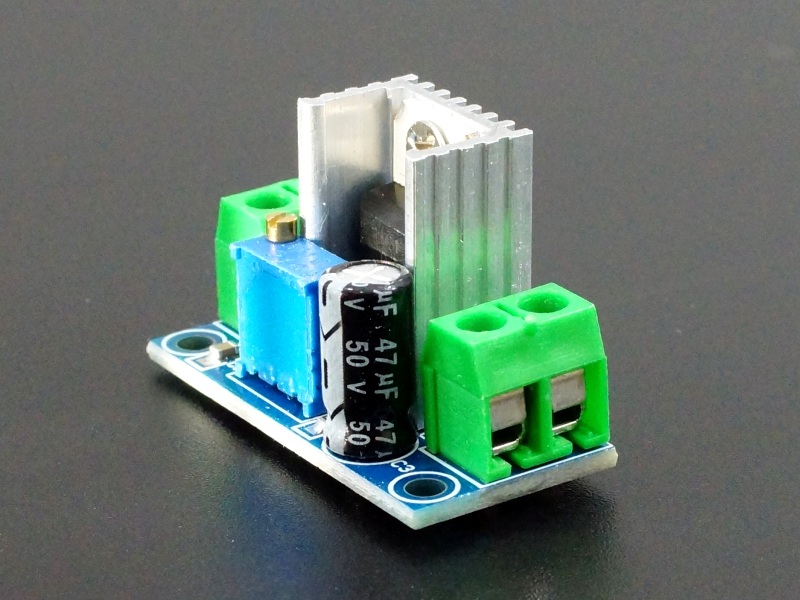
Inputs and output connections on the module are made via small screw terminals that you can connect to using regular hookup wire or the pin on male jumper wires.
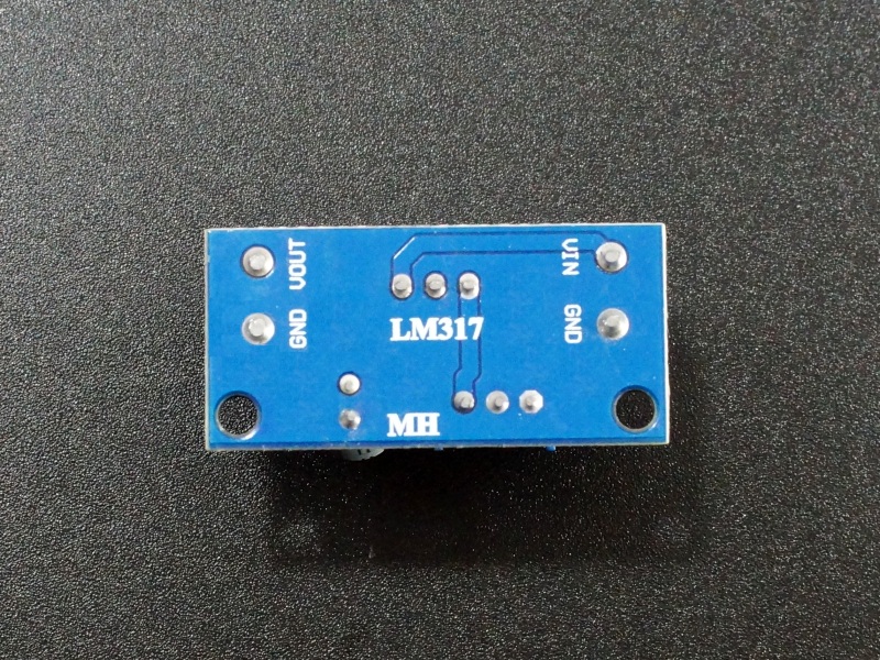
The connections are labeled on the back of the board due to the tight component packing on the top. The ground is common between the input and output terminals (not isolated).
Input Power
- VIN = Input Voltage
- GND = Ground for input
Output Power
- VOUT = Output Voltage
- GND = Ground for output
Note: Double-check that you have the input and output correctly hooked up before applying power or the module may be damaged.
OUR EVALUATION RESULTS:
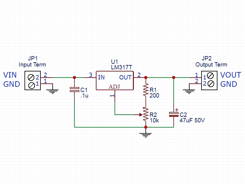
To wire an LM317 circuit on a breadboard takes an LM317 regulator IC, a resistor or two and a potentiometer if you want to be able to adjust the output voltage. An input/output filter cap is generally a good idea and you may need to add a heat sink to increase the power output capability. These circuits are easy and fun to create the first time or two, but after a while it is nice to just have the functionality without the fuss of needing to wire it up from scratch each time and that is where these modules come in handy and at a great price to boot!
As with any linear regulator, the power dissipation of the regulator is dependent on the difference between the input voltage and the output voltage along with the amount of current that is being drawn from the regulator. The larger the difference between the Vin and Vout, the higher the power dissipation which limits how much current can be drawn from the device.
To illustrate this concept, the table below gives some test results with the module using several different input voltages while the regulator output is set for 5V. As can be seen, with a 9V input the module can handle about 1A of continuous current before power dissipation gets too high without fan cooling. With a 32V input the module can only handle about 150mA. If this module was powered off our 7.5V AC Adapter which has a more ideal input/output voltage drop, it would get close to 1.5A with no cooling.
Since the module includes a heat sink, if a modest amount of air movement exists such as from a small fan, that allows the module to safely handle approximately double the amount of current before things get too toasty with all other things being equal.
Output Current vs Input / Output Voltage
| V In | V Out | V Difference | Max Current (ambient 25C) | Max Current (w/ fan cooling) |
| 9V | 5V | 4V | 1A | 1.5A + |
| 12V | 5V | 7V | 550mA | 1.3A |
| 32V | 5V | 27V | 150mA | 300mA |
BEFORE THEY ARE SHIPPED, THESE MODULES ARE:
- Output set for 5V
Notes:
- The tab of the LM317 is common with the output pin, so the heat sink is at the same voltage as the output is set for. Use care not to accidentally short the heat sink to ground.
- Under high current loads or with large input to output voltage differentials, the heat sink can get very hot, so use care when handling.
- Screw terminal connector colors may vary from picture.
Technical Specifications
| Maximum Ratings | ||
| VIN | Maximum Input Voltage | 40V |
| IO | Maximum Output Current | 1.5A |
| IPEAK | Peak Surge Current (typ) | 2.2A |
| Operating Ratings | ||
| VO | Output Voltage Range | 1.25 – 37V |
| VI – VO | Input to Output Differential | 3V min 40V max |
| IOR | Output Current Range | 0.01 to 1.5A |
| Dimensions | L x W x H | 35 x 17 x 23mm |
| Hole Distance | 30mm | |
| Datasheet | LM317 IC |

