LM2596S Adjustable DC-DC Step-Down SY-DC3003 Module
$3.95
Converts a 3.5 – 28V input down to a 1.25 – 26.5V output @ up to 2A with wired connections.
Out of stock
Description
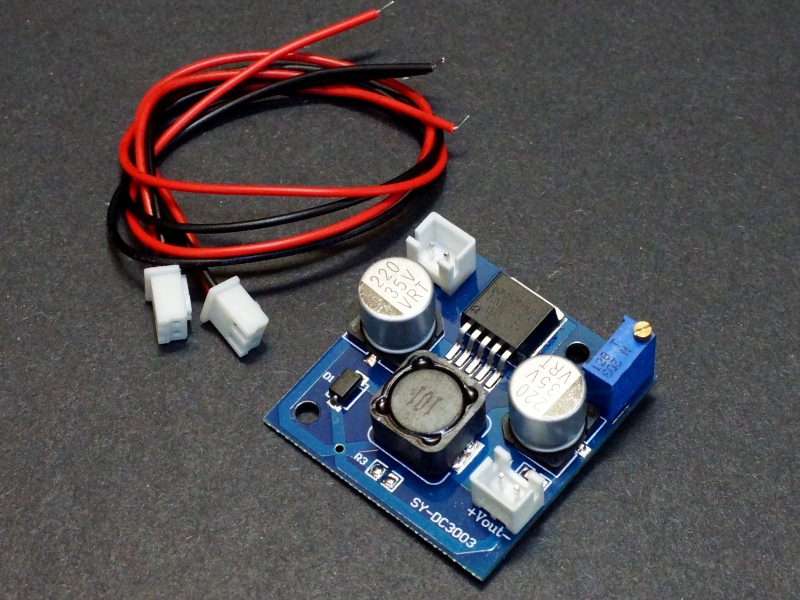
Similar to the standard LM2596S module except with wiring connections.
PACKAGE INCLUDES:
- LM2596S Adjustable DC-DC Step Down SY-DC3003 Module
- Qty 2 – JST XH2.54 2-pin female pig-tail cables
KEY FEATURES OF LM2596S ADJUSTABLE DC-DC STEP DOWN SY-DC3003 MODULE:
- LM2596S converter IC
- Output voltage adjustment
- Output current up to 2A (see chart below)
- Input voltage range 3.5 to 28V
- Output voltage range 1.25 to 26.5V
DC-DC Step-Down converters (also known as ‘Buck’ converters) convert a higher voltage to a lower voltage while also stepping up the available current.
This DC-DC Step-Down converter is adjustable and capable of outputting a voltage in the range of 1.25 to 26.5V at a continuous current of up to 1.5A and short-term current of up to 2A with a maximum power output of up to 24W. The input voltage must be higher than the output voltage.
The LM2596S converter IC has over current and thermal limiting features built-in.
The board has 2 holes which can be used for mounting it permanently if desired using two small M3 screws.
Voltage Adjustment
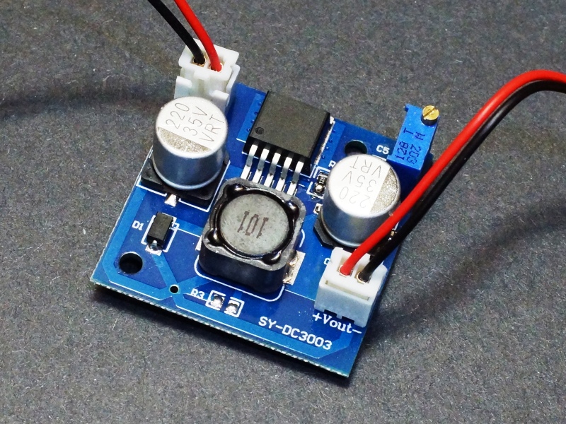
The module has a multi-turn potentiometer for adjustment of the output voltage.
Turning the pot CW decreases the output voltage while turning it CCW increases the output voltage.
The lowest output voltage is approximately 1.25V. The upper limit of the adjustment range will depend on the input voltage and is typically about 1.5V less than the input voltage. With a 12V input for instance, the upper output limit will be approximately 10.5V.
Module Connections
These are compact boards with connections made via the supplied XH2.54mm connectors. Input power is applied to the Vin connector while the output power is available on the Vout connector.
Connections are solder type so wires or header pins will need to be soldered to the board to connect power. The pinout is not on 0.1″ centers, so they cannot be plugged directly into a breadboard. For light duty use on a solderless breadboard where not much current is being pulled, short M/M jumper wires can work to connect power by soldering one end to the board and using the other end to plug into the breadboard. For short term use such as to test the module, alligator clips can be used to make the connections.
Vin
- + = Input voltage (3.5 to 28V)
- – = Ground for Input
Vout
- + = Output voltage (1.25 to 26.5V)
- – = Ground for Output
OUR EVALUATION RESULTS:
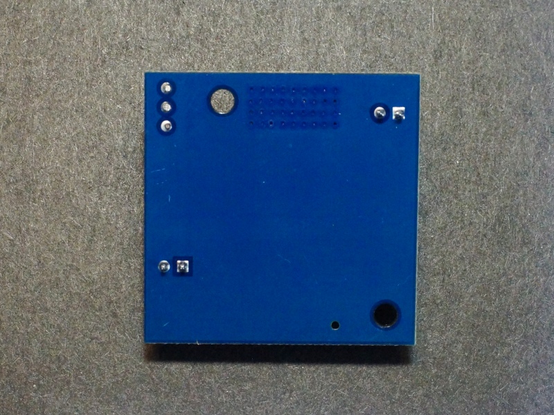
These are a little larger module than the standard LM2596S modules and have better ground plane heat sink capability than the standard module. The wiring connections can be handy for some types of applications
The weakest point of LM2596S modules in general is their output ripple which runs around 300mV on average. Not ideal for driving logic directly but works fine for driving a linear regulator, motors and similar applications. A filter capacitor on the output can also be used to help reduce the ripple.
In general at 1A, the module is very comfortably limping along. At 1.5A is it starting to get pretty warm but is still in a comfortable range. At 2A it is starting to get pretty toasty and in some cases too toasty
BEFORE THEY ARE SHIPPED, THESE MODULES ARE:
- Inspected
- Output is set for 5V
- Load tested 12V in, 5V out @ 2A
- Packaged in a high quality resealable ESD bag for protection and easy storage.
FURTHER READING
For more info on DC-DC Converters in general, see our DC-DC Converter Overview page.
Notes:
- Be sure to properly hook up the input and output connections before applying power to avoid possible damage to the module.
- Under higher current loads, the components can get fairly hot, so use care when handling.
Technical Specifications
| Maximum Ratings | ||
| VIN | Maximum Input Voltage | 28V (limited by capacitor voltage rating) |
| IO | Maximum Output Current (peak) | 2A |
| Operating Ratings | ||
| VO | Output Voltage Range | 1.25 – 26.5V |
| IO | Output Current (max continuous) | 1.5A |
| Switching Frequency | 150kHz | |
| Output Ripple | Varies depending on load | 50-400mV |
| Efficiency | Varies depending on load | 66%-86% (measured) |
| Electrical Isolation | Non-isolated | |
| Dimensions | L x W x H | 37 x 37 x 14mm (1.46 x 1.46 x 0.55″) |
| Datasheet | LM2596 IC |


