


LM2577 Adjustable DC-DC Boost Module
$7.95
Boosts a 3.5 – 35V input up to a 5 – 56V output @ up to 2A
Out of stock
Description
The LM2577 Adjustable DC-DC Boost Module can step-up the input voltage to a range of 5 – 56V at up to 2A.
PACKAGE INCLUDES:
- LM2577 Adjustable DC-DC Boost Module
KEY FEATURES OF LM2577 ADJUSTABLE DC-DC BOOST MODULE:
- Compact size
- LM2577 step-up converter IC with heatsink
- Output voltage adjustment
- Output current up to 2A (see chart below)
- Input voltage range 3.5 to 35V
- Output voltage range 5 to 56V
DC-DC Boost converters step up the input voltage to a higher voltage while also stepping down the available current since the module can’t output more power than it inputs.
This LM2577 based DC-DC boost converter is adjustable and capable of outputting a voltage in the range of 5 – 56V with an allowable input voltage range of 3.5 – 35V. The input voltage must be less than the output voltage. The output power is limited to about 9- 45W depending on the input and output voltage settings.
The LM2577 converter IC has current and thermal limiting and comes with a small heatsink applied.
An on-board red LED illuminates when power is applied.
Voltage Adjustment
The module has a multi-turn pot for adjustment of the output voltage.
Turning the pot CW increases the output voltage while turning it CCW decreases the output voltage.
The lowest output voltage will be determined by the input voltage as the output cannot be at a lower voltage than the input. The highest output voltage is 56V. While it is possible to adjust the output to be higher than 56V, permanent damage to the board will occur (so don’t do that!).
Module Connections
These are compact little boards with the input power applied to one end and output power available on the other end. With the silkscreen right-side up, the input will be on the right side.
Connections are solder type so wires or header pins will need to be soldered to the board to connect power. For light duty use on a solderless breadboard where not much current is being pulled, short M/M jumper wires can work to connect power by soldering one end to the board and using the other end to plug into the breadboard. For short term use such as to test the module, alligator clips can be used to make the connections.
Input Power
- IN+ = Input voltage (3.5 to 35V)
- IN- = Ground for Input
Output Power
- OUT+ = Output voltage (5 to 56V)
- OUT- = Ground for Output
Note: The grounds are not isolated so the IN- and OUT- are connected together on the module.
OUR EVALUATION RESULTS:
These modules are mainly handy when a higher voltage is needed and only a modest amount of current is required.
The LM2577 Adjustable DC-DC Boost Module maximum output power varies with the input voltage coming into the module and the output voltage setting.
The table has measurements taken at different input/output voltages to get a feel for the amount of power that can be pulled from the device under some typical operating conditions. Note that we aren’t testing it to the limits, these are just some representative operating points while keeping the IC well within a comfortable temperature range.
The thermal results are measured at the heat sink with an ambient temp of approx 25°C and no fan cooling. We tested to a maximum of 2A or the max supported by the module with the specific input / output settings as listed in the table. Efficiencies are also calculated.
Output Current vs Input / Output Voltage
| Voltage In | Voltage Out | Amps Out | Watts Out | Amps In | Watts In | Efficiency | Heat Sink Temp °C |
| 5 | 9 | 1.25 | 11.25 | 3.12 | 15.6 | 72% | 68 |
| 12 | 0.95 | 11.4 | 3.18 | 15.9 | 72% | 73 | |
| 24 | 0.45 | 10.8 | 2.94 | 14.7 | 74% | 72 | |
| 48 | 0.2 | 9.6 | 2.66 | 13.3 | 72% | 65 | |
| 9 | 12 | 2.0 | 24 | 3.20 | 28.8 | 83% | 59 |
| 24 | 0.9 | 21.6 | 2.86 | 25.74 | 84% | 69 | |
| 48 | 0.3 | 14.4 | 1.88 | 16.92 | 85% | 64 | |
| 12 | 24 | 1.2 | 28.8 | 2.74 | 32.88 | 88% | 66 |
| 48 | 0.48 | 23 | 2.22 | 26.64 | 87% | 70 | |
| 24 | 48 | 1.0 | 48.0 | 2.2 | 56.8 | 85% | 84+ |
Ripple/Noise
The amount of ripple and noise on the output varies depending on the input/output voltages, but it typically runs between 200-400mV with the worse case around 475mV as shown below.
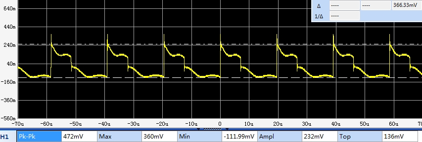
LM2577 Module Ripple
These boards do not have any dedicated mounting holes. Permanent mounting would require using double stick tape, Velcro or something similar.
BEFORE THEY ARE SHIPPED, THESE MODULES ARE:
- Inspected
- Output is set for 12V
- Load tested 5V in, 12V out @ 0.75A
- Packaged in high quality resealable ESD bags for protection and easy storage.
Notes:
- Be sure to properly hook up the input and output connections before applying power to avoid possible damage to the module.
- Do not adjust the output higher than 56V or damage to the module will result.
FURTHER READING
For more info on DC-DC Converters in general, see our DC-DC Converter Overview page.
Technical Specifications
| Maximum Ratings | ||
| VIN | Maximum Input Voltage | 35V |
| VIN | Maximum Output Voltage | 56V |
| IO | Maximum Output Current | 2A |
| Operating Ratings | ||
| Vi | Input Voltage Range | 3.5 – 35V |
| VO | Output Voltage Range | 5 – 56V |
| IO | Output Current Range (max continuous) | 0.2A – 2A (See table above) |
| Switching Frequency | 52kHz (measured) | |
| Output Ripple | Varies depending on load | 200-400mV |
| Efficiency | Varies depending on load | 72%-88% (measured) |
| Electrical Isolation | Non-isolated | |
| Dimensions | L x W x H | 45 x 30 x 15mm (1.75 x 1.2 x 0.6″) |
| Datasheet | LM2577 Chip |