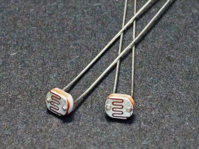
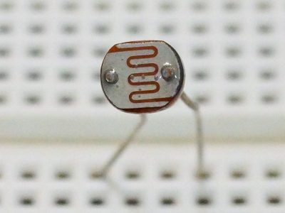
LDR – Light Dependent Resistor 20mm
$1.49
Extra large photosensor for detecting the presence and relative strength of light.
13 in stock
Description
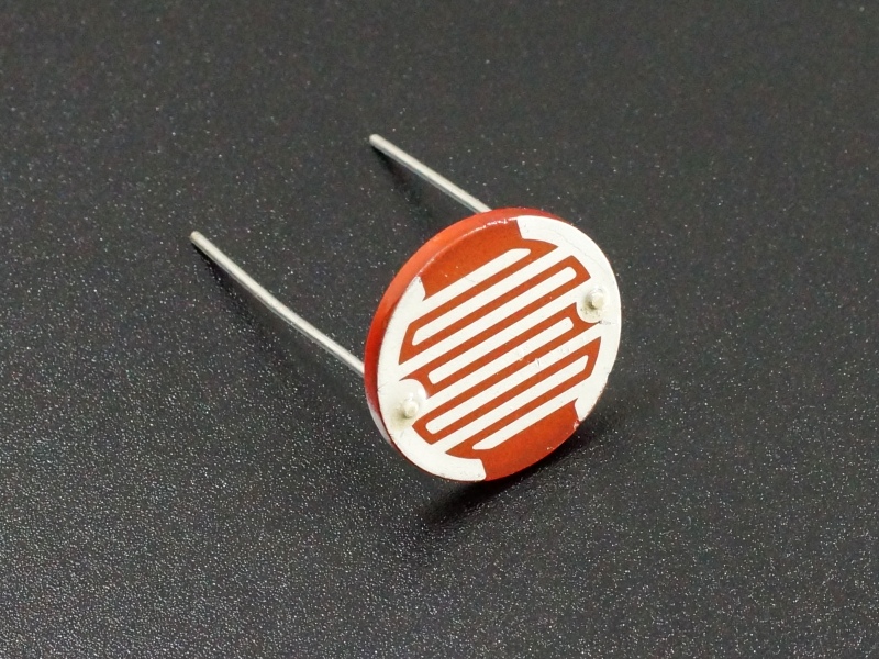
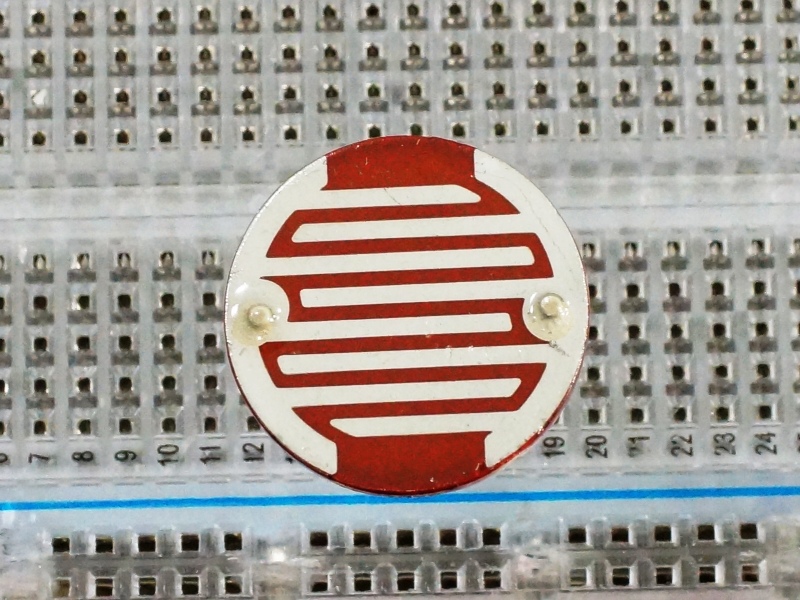
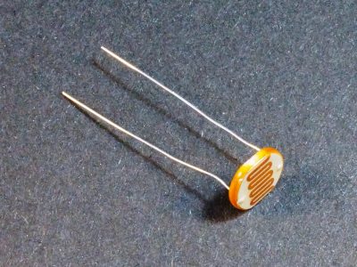
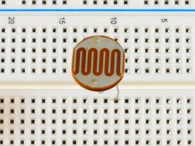
This extra large 20mm (3/4″) LDR (Light Dependent Resistor) is also called a photoresistor. An LDR is a resistor whose resistance changes with the amount of light striking it.
PACKAGE INCLUDES:
- 20mm LDR (Light Dependent Resistor)
KEY FEATURES OF LIGHT DEPENDENT RESISTORS:
As the strength of the light falling on the LDR increases, the resistance of the LDR gets lower.
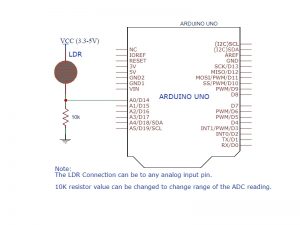
It is typical to put the LDR in series with a resistor to create a voltage divider and feed that output to an analog input on an MCU. The output will be a lower voltage when no light is striking the sensor and the voltage will increase as the light intensity increases.
These can be used in a variety of applications such as monitoring a pilot light, night light control, auto chicken coup door opener or anywhere that you want to detect a basic threshold of light and take some action.
Our Evaluation Results:
This is a basic light sensing component that can be used to experiment with a number of different types of applications which uses the presence or absence of light to take an action. They are robust devices that work well in final applications as well.
The leads on this device are very beefy and can be bent to support the sensor at any angle.
The output of the sensor is fairly linear, but the accuracy is not sufficient to measure the absolute strength of light. These are best used to detect the presence or absence of light or to a get rough idea of how much light is striking the sensor.
Here are some measured resistance values from a sample that we tested compared to LUX falling on the sensor
| LUX | LDR Resistance Value | Light Intensity |
| 0 | > 2M | Dark room |
| 10 | 12K | Very dim room |
| 300 | 2K | Moderate room light |
| 1000 | 900 | Overcast daylight |
| 20,000 | 100 | Next to fluorescent bulb |
The simple program below reads the output of the sensor using an analog port and outputs the raw data to the Serial Monitor window. Circuit hook-up is per the schematic shown above. Change lighting on the sensor to see the effect.
Changing the 10K resistor to a different value can be used to change the range of the analog output if desired. That may be useful when working with very bright or very dim light levels.
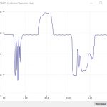
For fun, try changing the delay(1000) to something shorter such as delay(100) and use the Serial Plotter window to view the output while putting different light on the sensor. The plot shown to the right is an example output.
LDR Example Program
/*
Photoresistor Light Sensor Module Test

Basic code for reading the analog output of the light sensor module
*/
const int ANALOGPIN = A0;  // Set to any analog input pin
int rawValue = 0;          // Returned ADC reading from sensor

//===============================================================================
//  Initialization
//===============================================================================
void setup()
{
  pinMode (ANALOGPIN, INPUT);
  Serial.begin(9600);         // Set comm speed for debug window messages
}

//===============================================================================
//  Main
//===============================================================================
void loop()
{
  rawValue = analogRead (ANALOGPIN);  // Read sensor input
  Serial.print ("Reading Raw: ");
  Serial.println (rawValue);
  delay (1000);
}
Notes:
- None
Technical Specifications
| Operating Ratings | Max Voltage | 250V |
| Max Power Dissipation | 200mW | |
| Dark Resistance | > 1M Ohms | |
| Peak Detection Wavelength | 540nm (similar to human eye) | |
| Dimensions | Sensor Diameter | 20mm |
| Lead Diameter | 0.9mm (0.36″) | |
| Lead Length | 26mm (1″) |

