L298N Dual H-Bridge Motor Control Module
$4.95
Motor control module can drive 2 DC motors or 1 stepper motor at up to 2A.
11 in stock
Description
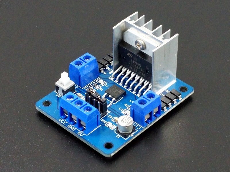
The L298N Dual H-Bridge Motor Control Module can be used to control 2 DC motors or 1 stepper motor at 2A continuous current per channel.
PACKAGE INCLUDES:
- L298N Dual H-Bridge Motor Control Module
KEY FEATURES OF L298N DUAL H-BRIDGE MOTOR CONTROL MODULE:
- Drive 2 DC motors with speed and direction control
- Drive 1 stepper motor
- 5 – 35V motor voltage range
- 2.5A peak current per channel (2A continuous)
The module can handle up to 2.5A peak per bridge or 2A continuous and 25W total power.
L298N modules do not have built-in current limiting, so they are best suited for DC motor control rather than stepper control, so that is what we are going to focus on here.
When used with DC motors, the H-Bridge drive arrangement allows the direction of the rotation of the motors to be changed. In addition PWM can be used to control the speed of the motors. This gives full control over the DC motors.
PWM stands for Pulse Width Modulation which means that the duty cycle (signal HIGH vs signal LOW) of the waveform can be changed. As the duty cycle is changed, the average DC voltage as seen by the motors also changes which changes the speed at which the motor turns. Motors require a minimum amount of voltage to start turning, so low PWM values may not move the motors but you may be able to hear the motors humming.
Input Power:
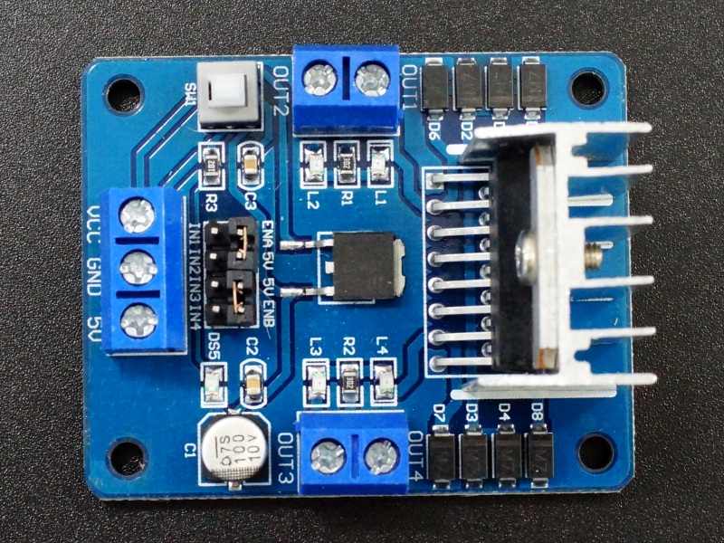
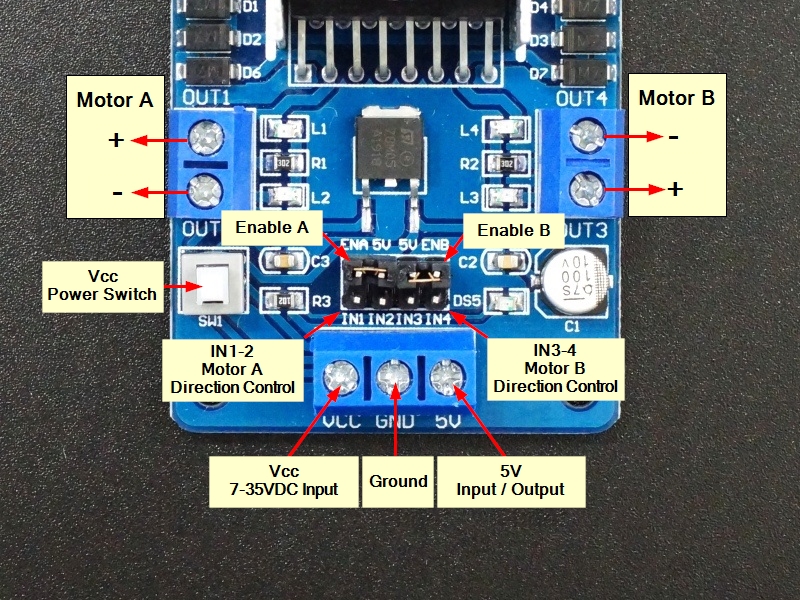
The module has a Vcc input terminal and a 5V terminal which can either be an input or an output. The module can be powered either by inputting 7 to 35V on the Vcc terminal or by inputting 5V on the 5V terminal.
There is a power button on the module that enables the Vcc input. When Vcc is enabled a red LED will light. If instead, you use the 5V power input, the switch is bypassed and the board will always be powered.
The Vcc input feeds a built-in 5V regulator which is used by the L298N chip. If the input voltage is in the range of 7 – 12VDC, there will be 5V available at the 5V terminal that can be used to power an Arduino or other 5V logic. The built-in 5V regulator can handle up to 400mA maximum. If Vcc is higher than 12VDC, it is not recommended to use the built-in 5V to power other devices to avoid possible overheating of the 5V regulator.
Using the Vcc input with a voltage between 7-12V gives the most flexibility when using this module and is the recommended mode to use.
NOTE: You cannot input voltages on both the Vcc and 5V terminals at the same time or damage may result.
Control Inputs:
The ENA & ENB pins are the enable pins for the 2 H-Bridge motor controllers in the L298N and are active HIGH. As shipped, these pins are jumpered to 5V (HIGH) which means they are constantly enabled. These jumpers are left on when using the module with a stepper motor. If using the module with DC motors they can be left on if it is always desired to run the motors at full speed. The motors can be stopped, run in fast forward or in fast reverse. Normally speed control is required so the jumpers are removed and the ENA / ENB pins are connected to PWM pins on the microcontroller to enact speed control over the motors using Pulse Width Modulation (PWM).
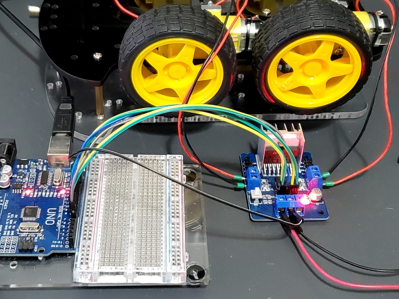
The drivers can each handle up to 2A. If the motors are on the smaller side such as is used on our Smart Car Chassis, two can be easily driven by each of the two drivers. This can be handy when using with a 4 wheel drive vehicle since you normally want both motors on the same side of the vehicle to be turning in unison anyway and that way one L298N module can be used to drive all 4 wheels.
The IN1, IN2, IN3 and IN4 are control pins that determine the configuration of the two H-Bridges in the device. The IN1 / IN2 pins control the ‘A’ motor bridge and the IN3 / IN4 pins control the ‘B’ motor bridge. The H-Bridge is what controls the direction that the motor turns as shown in the chart below. It can also be used for on/off control of desired, but normally the ENA / ENB enable lines are used for that purpose. There are green status LEDs on the IN1-4 lines near the motor terminal connections. When the control pins are HIGH, the associated LEDs are brightly lit. When they are LOW, the LEDs may either be off or dimly lit.
| IN1 / (IN3) | IN2 / (IN4) | |
| Forward Direction | HIGH | LOW |
| Reverse Direction | LOW | HIGH |
| Stopped | LOW | LOW |
| Stopped | HIGH | HIGH |
Note that the direction that the motors turn (forward vs reverse) with the above commands depends on how the ‘+’ and ‘-‘ leads of the motors are wired to the module. If they are turning backwards from what is expected, reverse the motor leads at the module.
Module Connections:
2 x 4 Header
- IN1 – Digital input for Motor A – Connect to a digital output pin on the microcontroller.
- IN2 – Digital input for Motor A – Connect to a digital output pin on the microcontroller.
- IN3 – Digital input for Motor B – Connect to a digital output pin on the microcontroller.
- IN4 – Digital input for Motor B – Connect to a digital output pin on the microcontroller.
- ENA – Enable for motor A, active HIGH. Remove jumper and connect to PWM pin on microcontroller if using speed control.
- 5V – Used to jumper ENA to HIGH
- 5V – Used to jumper ENB to HIGH
- ENB – Enable for motor B, active HIGH. Remove jumper and connect to PWM pin on microcontroller if using speed control.
1 x 3 Terminal
- VCC – Main power input. Can be 7-35V. 7-12V recommended. This is the voltage that is applied to the motor minus a 2V drop through the L298N driver.
- GND – System ground. Must be in common with the MCU ground.
- 5V – Input/output. Can input 5V if Vcc input is not used. If Vcc of 7-12V is input, 5V is available on this terminal to power other logic devices such as an Arduino.
1 x 2 Terminal (Motor A)
- OUT1 – Motor A ‘+’ positive lead
- OUT2 – Motor A ‘-‘ negative lead
1 x 2 Terminal (Motor B)
- OUT3 – Motor A ‘+’ positive lead
- OUT4 – Motor A ‘-‘ negative lead
OUR EVALUATION RESULTS:
These modules work well and are straightforward to use. The logic is easy enough that a library is not needed to implement the software to control them.
The program below is a simple program to illustrate the control of DC motors. It moves the motors through a repeating sequence of running them both forward, then backwards, then in opposite directions. It then ramps the motor speed up and then back down in both forwards and reverse directions.
The IN1-4 digital pins can be connected to any digital pins that are available on the MCU. The ENA and ENB pins must be connected to PWM pins as we will use them for speed control. The default program settings are as follows:
- ENA – Pin 10 (must be PWM capable)
- IN1 – Pin 9
- IN2 – Pin 8
- ENB – Pin5 (must be PWM capable)
- IN3 – Pin 7
- IN4 – Pin 6
You will also need a common ground between the MCU and the motor controller ground terminal.
All of the low level motor control is done in a function called Motor. The Motor function takes the following inputs:
- mot = Motor to control. This can be ‘A’ for motor A or ‘B’ for motor B or ‘C’ to control both. Note that the single quotes are needed to denote that we are passing type char
- dir = Direction of motor. This can be ‘F’ for forward or ‘R’ for reverse. Again, but sure to use the single quotes.
- speed = Speed of motor. The value passed to the function is expressed in a range of 0-100%. That value is remapped to 0-255 for PWM control. The remapping ignores speed values that are too low to make the motors turn using the constant MIN_SPEED which in our example is set to 27, but 0 still means 0 to stop the motors. The optimum MIN_SPEED value for a particular setup will depend on the motors being used and the voltage at which they are being powered and is best determined experimentally.
L298N Dual H-Bridge Motor Control Module Example Program
/*
*  L298N Dual H-Bridge Test - DC Motors
*  Code for exercising the L298N Motor Control module.
*  The low level motor control logic is kept in the function 'Motor'
*/
//  IN1-4 can be connected to any digital pins on microcontroller
//  ENA and ENB must be connected to PWM pins.
//  Motor A
int const ENA = 10;  // Must be PWM pin
int const IN1 = 9;
int const IN2 = 8;
//  Motor B
int const ENB = 5;  // Must be PWM pin
int const IN3 = 7;
int const IN4 = 6;

int const MIN_SPEED = 27;   // Set to minimum PWM value that will make motors turn
int const ACCEL_DELAY = 50; // delay between steps when ramping motor speed up or down.
//===============================================================================
//  Initialization
//===============================================================================
void setup()
{
  pinMode(ENA, OUTPUT);   // set all the motor control pins to outputs
  pinMode(ENB, OUTPUT);
  pinMode(IN1, OUTPUT);
  pinMode(IN2, OUTPUT);
  pinMode(IN3, OUTPUT);
  pinMode(IN4, OUTPUT);
  Serial.begin(9600);     // Set comm speed for serial monitor messages
}
//===============================================================================
//  Main
//===============================================================================
void loop()
{
  // This  will run both motors in both directions at a fixed speed
  // First go Forward at 75% power for 2 seconds
  Motor('C', 'F', 75);
  delay(2000);
  // now change motor directions to reverse and run at 75% speed
  Motor('C', 'R', 75);
  delay(2000);
  // now run motors in opposite directions at same time at 50% speed
  Motor('A', 'F', 50);
  Motor ('B', 'R', 50);
  delay(2000);
  // now turn off both motors
  Motor('C', 'F', 0);
  delay(2000);

  // Run the motors across the range of possible speeds in both directions
  // Maximum speed is determined by the motor itself and the operating voltage

  // Accelerate from zero to maximum speed
  for (int i = 0; i <= 100; i++)
  {
    Motor('C', 'F', i);
    delay(ACCEL_DELAY);
  }
  delay (2000);
  // Decelerate from maximum speed to zero
  for (int i = 100; i >= 0; --i)
  {
    Motor('C', 'F', i);
    delay(ACCEL_DELAY);
  }
  delay (2000);
  // Set direction to reverse and accelerate from zero to maximum speed
  for (int i = 0; i <= 100; i++)
  {
    Motor('C', 'R', i);
    delay(ACCEL_DELAY);
  }
  delay (2000);
  // Decelerate from maximum speed to zero
  for (int i = 100; i >= 0; --i)
  {
    Motor('C', 'R', i);
    delay(ACCEL_DELAY);
  }
  // Turn off motors
  Motor('C', 'F', 0);
  delay (2000);
}
/*
 * Motor function does all the heavy lifting of controlling the motors
 * mot = motor to control either 'A' or 'B'.  'C' controls both motors.
 * dir = Direction either 'F'orward or 'R'everse
 * speed = Speed.  Takes in 1-100 percent and maps to 0-255 for PWM control.
 * Mapping ignores speed values that are too low to make the motor turn.
 * In this case, anything below 27, but 0 still means 0 to stop the motors.
 */
void Motor(char mot, char dir, int speed)
{
  // remap the speed from range 0-100 to 0-255
  int newspeed;
  if (speed == 0)
    newspeed = 0;   // Don't remap zero, but remap everything else.
  else
    newspeed = map(speed, 1, 100, MIN_SPEED, 255);

  switch (mot) {
    case 'A':   // Controlling Motor A
      if (dir == 'F') {
        digitalWrite(IN1, HIGH);
        digitalWrite(IN2, LOW);
      }
      else if (dir == 'R') {
        digitalWrite(IN1, LOW);
        digitalWrite(IN2, HIGH);
      }
      analogWrite(ENA, newspeed);
      break;

    case 'B':   // Controlling Motor B
      if (dir == 'F') {
        digitalWrite(IN3, HIGH);
        digitalWrite(IN4, LOW);
      }
      else if (dir == 'R') {
        digitalWrite(IN3, LOW);
        digitalWrite(IN4, HIGH);
      }
      analogWrite(ENB, newspeed);
      break;

    case 'C':  // Controlling Both Motors
      if (dir == 'F') {
        digitalWrite(IN1, HIGH);
        digitalWrite(IN2, LOW);
        digitalWrite(IN3, HIGH);
        digitalWrite(IN4, LOW);
      }
      else if (dir == 'R') {
        digitalWrite(IN1, LOW);
        digitalWrite(IN2, HIGH);
        digitalWrite(IN3, LOW);
        digitalWrite(IN4, HIGH);
      }
      analogWrite(ENA, newspeed);
      analogWrite(ENB, newspeed);
      break;
  }
  // Send what we are doing with the motors out to the Serial Monitor.

  Serial.print ("Motor: ");
  if (mot=='C')
      Serial.print ("Both");
    else
      Serial.print (mot);
  Serial.print ("  Direction: ");
  Serial.print (dir);
  Serial.print ("  Speed: ");
  Serial.print (speed);
  Serial.print ("  Mapped Speed: ");
  Serial.println (newspeed);
}
Before they are shipped, these modules are:
- Sample inspected and tested per incoming shipment.
Notes:
- None
Technical Specifications
| Operating Ratings | ||
| Voltage range (Vcc) | 5 – 35 VDC | |
| Recommended voltage range (Vcc) | 7 – 12 VDC | |
| Voltage range (5V) | 4.5 – 5.5 VDC | |
| Max current per bridge | 2 A | |
| Max power of module | 25 W | |
| Dimensions | ||
| Driver Board (L x W x H) | 54 x 44 x 28 mm (2.1 x 1.7 x 1.1″) | |
| Datasheet | L298N |

