ISD1820 Voice Record and Playback Module
$3.95
Record up to 10 seconds of audio and then play it back under MCU or manual control.
12 in stock
Description
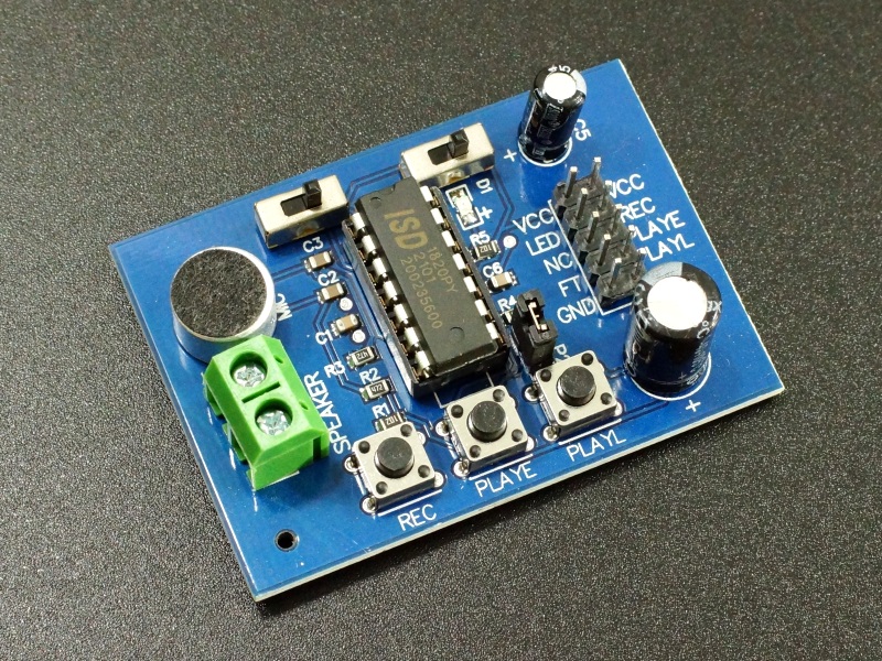
The ISD1820 Voice Record and Playback Module provides a simple way to record up to 10 seconds of audio and then play it back under MCU or manual control.
PACKAGE INCLUDES:
- ISD1820 Voice Record and Playback Module
KEY FEATURES OF ISD1820 VOICE RECORD AND PLAYBACK MODULE:
- Record and playback up to 10 seconds of audio.
- Pushbutton and MCU controllable
- Edge or level activated playback
- Built-in microphone
- On-chip 8 ohm speaker driver
- Duration and sample rate can be modified up to 20 seconds with resistor change
- Auto power down mode
- 2.6 -5V operation
With the built-in microphone, you can record one message that is up to 10 seconds long. This can be extended up to 20 seconds with a resistor change. The message can be rerecorded up to 100,000 times and is non-volatile.
A small built-in audio amplifier can drive an 8 ohm speaker.
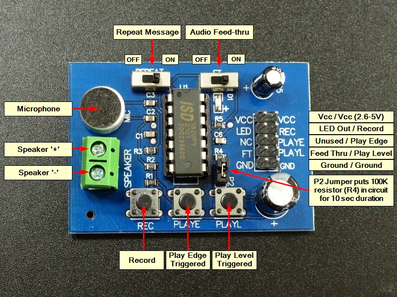
The main features of the module are shown below. Functions such as Record, PlayE and PlayL can be activated by pushing a button or input a logic HIGH on the header pin with the same name.
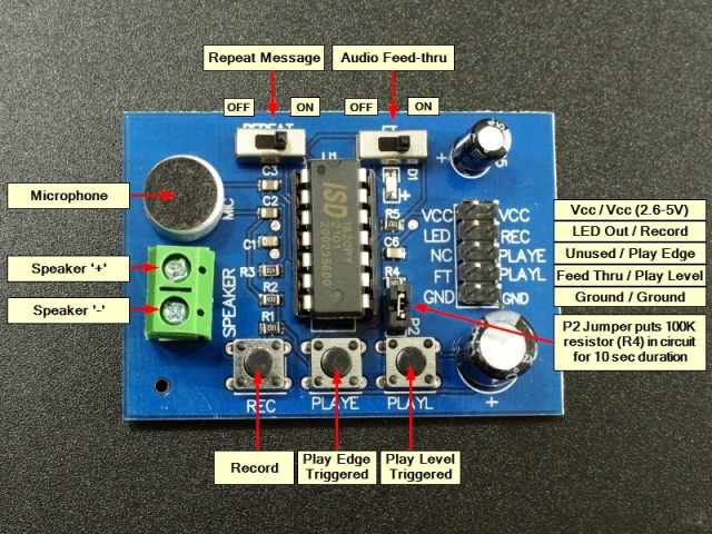
| REC | RECORD – Pin is active HIGH to start recording and must remain high while the recording is in process. The red LED will light while recording. Once the pin goes LOW or it runs out of memory, an End-Of-Message (EOM) marker is automatically recorded.
Pressing and holding down the pushbutton will also record a message. Release the button to stop the recording. |
| PLAYE | PLAY Edge – Pin is edge activated when it transitions to HIGH. The recording will play until the EOM is reached. The pin can be set LOW while message plays and it will not terminate the message. When EOM is reached the red LED will flash.
Pressing the pushbutton will play the entire recorded message. |
| PLAYL | PLAY Level – Pin is active HIGH. When pin goes HIGH, the message will play until the pin is set back to LOW or the EOM is reached.
Pressing the pushbutton will play the recorded message until the button is released or the EOM is reached. |
| REPEAT | REPEAT Switch – if moved to the right will play the recorded message continuously. |
| FT | FT Switch – if moved to the right will enable a Feed Thru mode of operation. In this mode of operation, any audio picked up by the mic will be sent directly out to the speaker |
| LED | LED Output – Normally HIGH, goes LOW when LED is lit |
| VCC | VCC can range from 2.6 to 5.5V. Only one VCC pin needs to be connected |
| GND | Ground should be common with the uC. Only one GND pin needs to be connected |
| NC | No Connect – Unused |
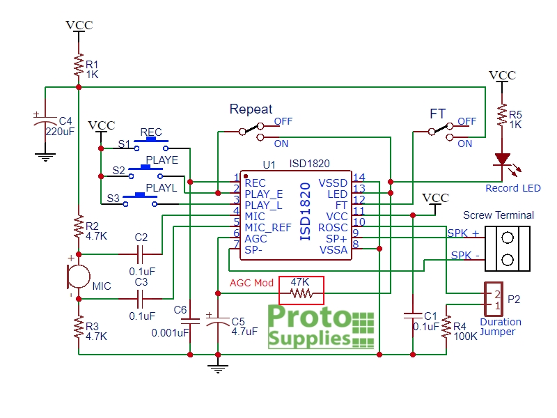
The ISD1820 chip has a Resistor Controlled Oscillator input (ROSC) input. A resistor placed between the ROSC pin and ground sets the oscillator frequency and therefore sample rate and thus the maximum duration of the audio. As per the table below, a tradeoff can be made between using a shorter duration recording, but with a higher sample rate and bandwidth or the duration can be extended up to 20 seconds with a lower sample rate and bandwidth.
The module ships with a 100K resistor in location R4 that is connected to the ROSC pin on the ISD1820P chip. It is put into the circuit with the jumper at location P2. 100K is what sets the 10 second duration for the recording. R4 can be replaced, or the jumper can be removed and a different value can be jumpered from the header pin next to R4 to ground to change the recording characteristics per the table below.
| ROSC | Duration | Sample Rate | Bandwidth |
| 80K Ohm | 8 Secs | 8.0kHz | 3.4kHz |
| 100K Ohm | 10 Secs | 6.4kHz | 2.6kHz |
| 120K Ohm | 12 Secs | 5.3kHz | 2.3kHz |
| 160K Ohm | 16 Secs | 4.0kHz | 1.7kHz |
| 200K Ohm | 20 Secs | 3.2kHz | 1.3kHz |
It is also possible to record at one rate and play back at another. That will serve to speed up or slow down the playback which might be useful for creating sound effects. A pot can be wired in for this purpose.
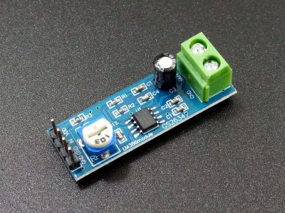
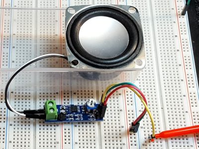
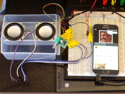
The power output can drive a small speaker or the output can be used to drive the input of an audio amplifier if a louder sound is desired. If driving the input of an amplifier, connect just one of the speaker outputs to the input of the amplifier. A fairly large 10-100uF capacitor should be in series between the speaker output and the input of the amplifier to remove any DC offset.
OUR EVALUATION RESULTS:
The beauty of this module is that it is simple to use as it doesn’t have a lot of options to complicate things. We embedded one in a Zombie operation game for a sound effect when the tweezers touched the side and it is perfect for Halloween effects and similar applications.
The sound quality is fair and good enough for most applications that would make use of this device.
To test the device, just apply power and ground to the header pins and hookup a speaker to the screw terminals. Pressing PLAYE will play anything that may have been pre-recorded on the device during testing. To make your own recording, press and hold the REC button and speak into the mic. Pressing PLAYE should replay the audio that you just recorded. If it doesn’t seem to be working, verify that the Audio Feedthru switch is in the OFF position.
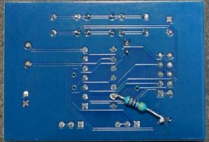
The main complaint about this module is that the audio playback volume is on the weak side. To improve that somewhat, a 47K ohm resistor is added from the AGC Input to the LED Output pin. This ensures that the AGC circuit keeps a higher level during recording and hence the playback volume is also increased. Recording close to the microphone while speaking or playing the sound loudly will also help with the volume
The resistor is added to the back of the board.
Mini MP3 and WAV File Player
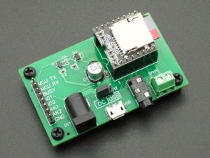
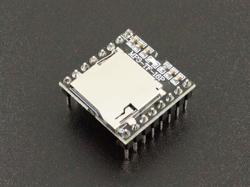
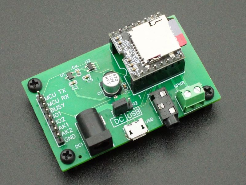
If you are working with sounds that are prerecorded in MP3 or WAV file format, another option to consider is our Mini MP3 and WAV file player which also has a baseboard available for easy use. This player plays files from an SD card so switching between multiple different sounds or music are possible and a 32GB SD card can support hours of audio recordings. The module can drive a speaker directly at up to 3W and also has an analog output that can be used to drive powered speakers like PC speakers, so achieving loud volume is not an issue. It is designed to be controlled by a microcontroller.
Click on pic for more information.
BEFORE THEY ARE SHIPPED, THESE MODULES ARE:
- Resistor added to AGC circuit
- Basic functionality tested.
- Packaged in a resealable ESD bag for protection and easy storage.
Notes:
- The attached datasheet is for the ISD1806 /1810 series, so some specs will be different. The main thing to note is that the ISD1820 can be operated at 5V. We have tested it to 5.5V without any problems noted.
Technical Specifications
| Operational Ratings | ||
| Vcc | Vcc Power Range | 2.6 – 5V |
| Recording time | Controlled by R4 value | 8-20 seconds |
| Speaker impedance | 8 Ohm minimum | |
| Dimensions | ||
| PCB (L x W x H) | 55 x 38 x 16mm (2.2 x 1.5 x 0.63″) | |
| Country of Origin | China | |
| Datasheet | Note: This is 1800 Series, not 1820 | ISD1800 Series |

