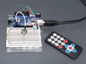
IR Remote Control Kit
$2.25 Original price was: $2.25.$1.95Current price is: $1.95.
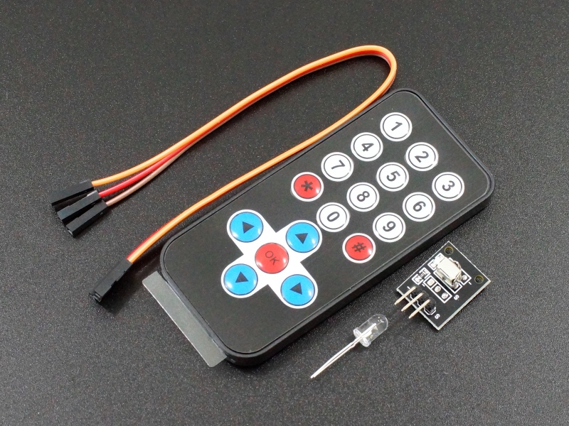
Kit includes remote control with battery, IR sensor and IR transmitter LED.
10 in stock
Description
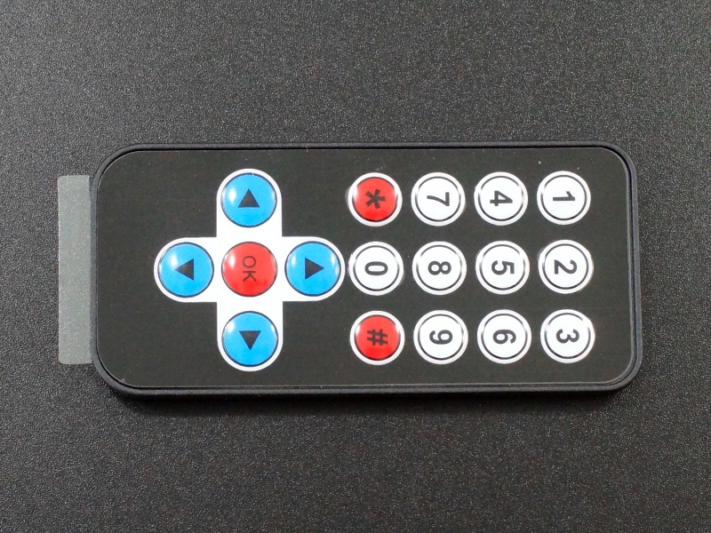
This IR Remote Control Kit is ideal for implementing an IR remote control for many projects including controlling robotics since the remote includes direction keys and basic number keys without all the unnecessary key clutter found on remotes used for TV style control.
PACKAGE INCLUDES:
- IR Remote Control w/ battery
- IR Receiver Module
- IR Emitter / Transmitter LED
- 3-Wire F/F Jumper Cable 8″
KEY FEATURES OF IR REMOTE CONTROL KIT:
- 8 meter range
- Robotic oriented buttons
- NEC control codes
- Includes IR receiver module for use with MCU
- Includes IR transmitter LED for implementing IR control via an MCU
- Includes battery
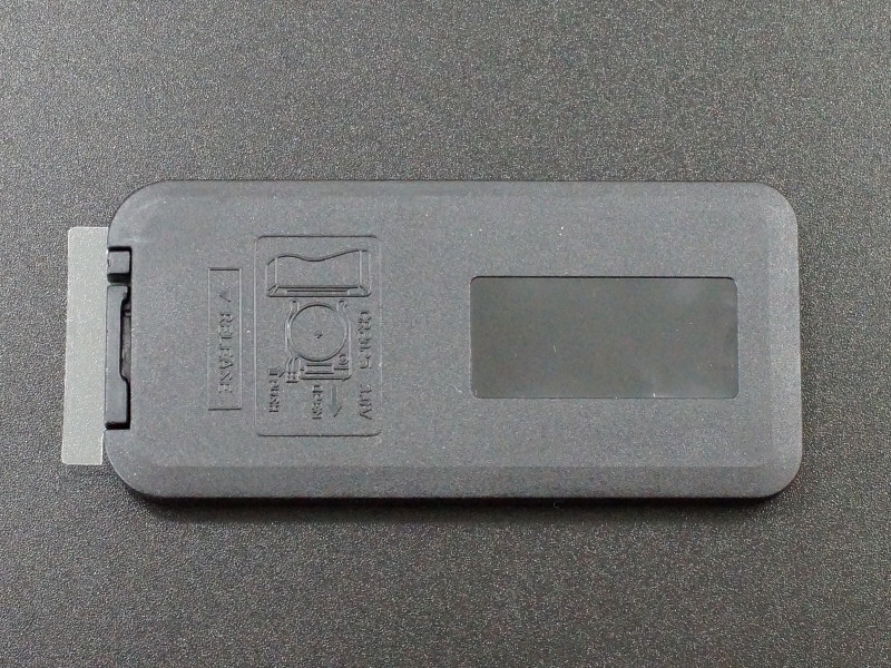
The IR remote has a minimum control range of about 8 meters (24 feet). It comes with a CR2025 battery installed. Just be sure to pull out the plastic insert tab sticking out of the end of the remote to enable the battery.
The remote uses NEC codes. The specific hex codes used for each remote control button are listed in the table below. When used within a program, hex codes use the prefix ‘0x’ to signify they are a hex value, so the ‘1’ button would be written as ‘0x45’ within a program.
IR Remote Control Codes
| Key | IR Code | Key | IR Code |
| 1 | 0x45 | 0 | 0x19 |
| 2 | 0x46 | * | 0x16 |
| 3 | 0x47 | # | 0x0D |
| 4 | 0x44 | UP | 0x18 |
| 5 | 0x40 | RIGHT | 0x5A |
| 6 | 0x43 | DOWN | 0x52 |
| 7 | 0x07 | LEFT | 0x08 |
| 8 | 0x15 | OK | 0x1C |
| 9 | 0x09 |
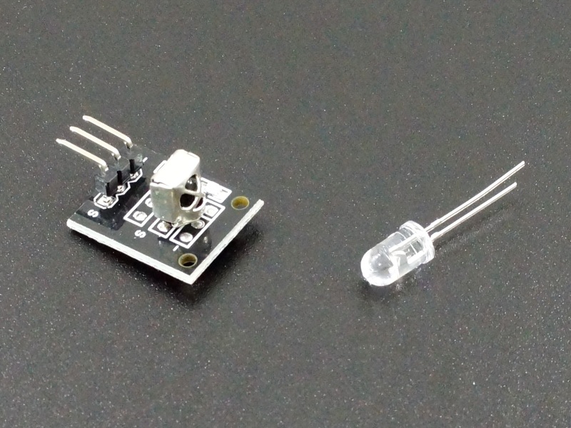
The IR Receiver module that comes in the kit provides the receiving end of the IR control setup if you need one. Just apply 3.3 – 5V and ground and hook-up the signal output pin to a digital input pin on the MCU for reading the received codes. It comes with a 3-wire female-female jumper cable that can be used for hookup in some installations. Click on the pic to see the product page for more information about this module.
1 x 3 Header
- ‘-‘ pin = Connect to Ground
- Center pin = Connect to Vcc (3.3-5V)
- ‘S’ pin = Connect to digital input pin on MCU
The kit also includes an IR emitter / transmitter LED. This can be handy if you want to try using the MCU to replace the IR remote control by controlling the IR directly.
The LED works like any LED, except the output is in the invisible IR range. If using the IR LED with an MCU, be sure to limit the current to about 20mA by using about a 180 ohm current limiting resistor to avoid damage to the MCU assuming the MCU can support 20mA on its output pins. The IR LED itself can handle up to about 50mA.
Click here for more info on the IR emitter LED.
Click here for more info on the IR Receiver Module.
OUR EVALUATION RESULTS:
These work great for implementing basic IR Remote Control for various projects.
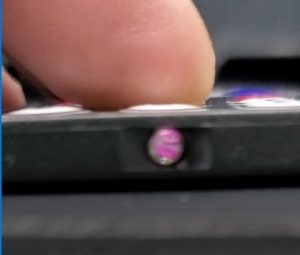
To check to see if the remote control is working, you can look at the IR LED using a cell phone camera while you push buttons on the remote as shown below. Cell phone cameras are sensitive to IR light and will make it visible when looking at the LED through the camera. The same trick will work with the IR LED that comes in the kit if you try to use it.
The program below sets up the basic framework to detect IR commands and react to them. In this case, we are just printing the raw data and command we receive to the Serial Monitor window, but it would be easy to add statements to the switch/case statement to add functionality such as motor control.
The program uses the IRremote.h library which comes with the Arduino IDE to do most of the heavy-lifting for us. This library was recently updated and the example has been updated to work with the new library.
Connect the IR receiver to power and ground to match the MCU. Connect the S pin to pin 2 on the MCU, though this can be changed to any other digital pin for our example here.
Download the program below and open the Serial Monitor window and set for 115200 baud.
Point the IR remote at the sensor and press the various buttons to see the result in the Serial monitor window.
IR Remote Control Kit Example Program
/*
 * IR Remote Control Test
 *
 * Receive and decode each of the key presses from the remote
 * Print the raw data amd key received to the Serial monitor window
 *
 * Uses the IRremote.hpp library
 */

// Specify which protocol(s) should be used for decoding.
//  This must be done before the #include <IRremote.hpp>
#define DECODE_NEC

#include <Arduino.h>
#include <IRremote.hpp>

#define IR_RECEIVE_PIN   2

void setup() {
    Serial.begin(115200);

    // Start the receiver
    IrReceiver.begin(IR_RECEIVE_PIN, LED_BUILTIN);
}

void loop() {
    /*
     * Check if received data is available and if yes, try to decode it.
     * Decoded result is in the IrReceiver.decodedIRData structure.
     *
     * E.g. command is in IrReceiver.decodedIRData.command
     * address is in command is in IrReceiver.decodedIRData.address
     * and up to 32 bit raw data in IrReceiver.decodedIRData.decodedRawData
     */
    if (IrReceiver.decode()) {

        // Print a short summary of received data
        IrReceiver.printIRResultShort(&Serial);

        delay(250);  // Delay to reduce the number of false repeats
         // !!!Important!!! Enable receiving of the next value,
         // since receiving has stopped after the end of the current received data packet.
        IrReceiver.resume(); // Enable receiving of the next value

        // Perform actions according to the received command
        translateIR();
        Serial.println();
    }
}
//===============================================================================
//  Subroutine to handle the command that was received
//===============================================================================
void translateIR()
{
  Serial.print("Button Pushed: ");
  // IrReceiver.decodedIRData.command holds the hex value of command received
  switch(IrReceiver.decodedIRData.command)
  {
  case 0x18:
    Serial.println("UP");
    break;
  case 0x08:
    Serial.println("LEFT");
    break;
  case 0x1C:
    Serial.println("-OK-");
    break;
  case 0x5A:
    Serial.println("RIGHT");
    break;
  case 0x52:
    Serial.println("DOWN");
    break;
  case 0x45:
    Serial.println("1");
    break;
  case 0x46:
    Serial.println("2");
    break;
  case 0x47:
    Serial.println("3");
    break;
  case 0x44:
    Serial.println("4");
    break;
  case 0x40:
    Serial.println("5");
    break;
  case 0x43:
    Serial.println("6");
    break;
  case 0x07:
    Serial.println("7");
    break;
  case 0x15:
    Serial.println("8");
    break;
  case 0x09:
    Serial.println("9");
    break;
  case 0x16:
    Serial.println("*");
    break;
  case 0x19:
    Serial.println("0");
    break;
  case 0x0D:
    Serial.println("#");
    break;
  default:
    Serial.println("Unidentified button");
  }
}
BEFORE THEY ARE SHIPPED, THESE MODULES ARE:
- Sample tested per incoming shipment
Notes:
- None
Technical Specifications
| Maximum Ratings | ||
| Vcc | 3.3 – 5V | |
| IMax | Maximum Current Draw (remote control) | < 5 mA (when button pushed) |
| Operating Ratings | ||
| Frequency | Modulation Center Frequency | 38 kHz |
| IR Wavelength | Nominal | 940 nm |
| Maximum Distance | Typical | > 8 meters |
| Effective Angle | 60 degrees (+/- 30 degrees) | |
| Battery | CR2025 (coin type) | |
| Dimensions | L x W x H (Remote Control) | 86mm x 40mm x 7mm (3.4 x 1.6 x 0.28″) |
| Country of Origin | China |

