HT16K33 LED Controller Module
$2.59
Multi-function LED controller with keyboard scanner and I2C interface.
Out of stock
Description
The HT16K33 is a 7-segment, alphanumeric and matrix LED controller with keyboard scanner and I2C interface.
PACKAGE INCLUDES:
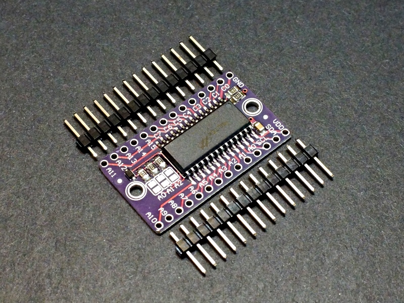
- HT16K33 Module
- Qty 2 – 14-pin male header strips
KEY FEATURES OF HT16K33 LED CONTROLLER MODULE:
- 16 x 8 segment driver
- 13 x 3 matrix key scanning w/ interrupt output
- 16-level dimming
- Built-in clock and display update
- I2C interface
- 5V operation
HT16K33 Chip:
The module uses the 28-pin HT16K33 LED controller / driver chip from Holtek.
The HT16K33 is designed as a multi-functional device for driving a number of LED display applications including dot matrix, 7-segment and alphanumber 14-segment displays. It also includes a keyboard scanner by multiplexing the same pins for both driving the display and looking for key presses.
It can address up to 16 rows with 8 common pins, so can support up to 128 LEDs in a matrix or eight 7-segment or aphanumeric displays.
Communications with the chip is via I2C interface.
I2C Interface
The module has an easy to use I2C interface.
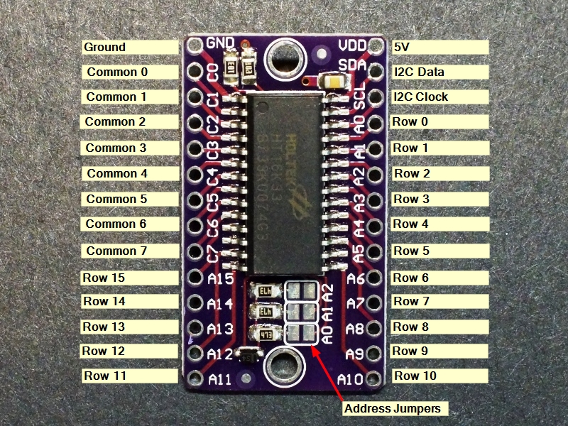
The default I2C address is 0x70. Address lines A0-A2 allow the address to be set to the range of 0x70 – 0x77 by solder bridging the pads to pull that pin high. Bridging all 3 pads results in the address 0x77.
The I2C lines have 10K pull-up resistors included on the module.
Module Connections
The board has two 14-pin male headers. The module brings the chip pins directly out to the corresponding header pin.
1 x 14 Header (left)
- GND = Vss / Ground
- C0 = COM0 / AD – Common output pin 0. Address source pin
- C1 = COM1 / KS0 – Common output pin 1. Key Source output 0
- C2 = COM2 / KS1 – Common output pin 2. Key Source output 1
- C3 = COM3 / KS2 – Common output pin 3. Key Source output 2
- C4 = COM4 – Common output pin 4.
- C5 = COM5 – Common output pin 5.
- C6 = COM6 – Common output pin 6.
- C7 = COM7 – Common output pin 7.
- A15 = ROW15 / K13 / INT – Row 15 driver. Key 13 input, Interrupt output
- A14 = ROW14 / K12 – Row 14 driver. Key 12 input
- A13 = ROW13 / K11 – Row 13 driver. Key 11 input
- A12 = ROW12 / K10 – Row 12 driver. Key 10 input
- A11 = ROW11 / K9 – Row 11 driver. Key 9 input
1 x 14 Header (right)
- VDD = Power (4.5V – 5.5V)
- SDA = I2C Data Input/Output
- SCL = I2C Clock
- A0 = ROW0 / A2 – Row 0 driver. Address bit 2
- A1 = ROW1 / A1 – Row 1 driver. Address bit 1
- A2 = ROW2 / A0 – Row 2 driver. Address bit 0
- A3 = ROW3 / K1 – Row 3 driver. Key 1 input
- A4 = ROW4 / K2 – Row 4 driver. Key 2 input
- A5 = ROW5 / K3 – Row 5 driver. Key 3 input
- A6 = ROW6 / K4 – Row 6 driver. Key 4 input
- A7 = ROW7 / K5 – Row 7 driver. Key 5 input
- A8 = ROW8 / K6 – Row 8 driver. Key 6 input
- A9 = ROW9 / K7 – Row 9 driver. Key 7 input
- A10 = ROW10 / K8 – Row 10 driver. Key 8 input
Assembling the Module
The module comes with 2 strips of male headers. These can be soldered on for use on a breadboard, or you can attach wires directly to the board depending on what your application requires.
When soldering the headers on, it is recommended to insert the headers into a solderless breadboard or perf board first to hold them in alignment while soldering.
OUR EVALUATION RESULTS:
These are useful modules for a number of LED display driver applications.
This is the same part that is used on a lot of the Adafruit LED display modules and so they have good library support for the device which is available through the Arduino IDE. The keyboard scanning function is not supported in their libraries.
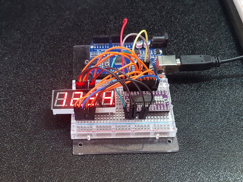
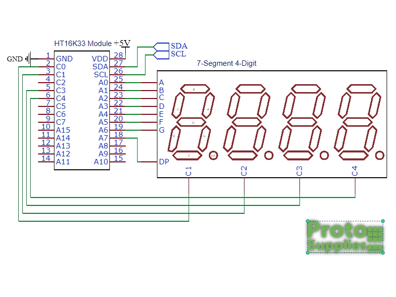
The schematic for the example used is shown here.
Note that the common cathode connections for the LED module may be labeled as G1-G4, C1-C4 or other similar notation. When wiring things up, skip connecting to C2 on the HT16K33 module if using a module which does not have the clock colon as we are using here.
Connect A0 thru A6 to the LED segments A thru G respectively.
Connect C0, C1, C3 and C4 to the common cathodes of the LED. These may be labeled as G1-G4 or something similar. Note that we are skipping C2 which is used to drive the colon when using a clock style 7-segment module
Connect A7 to the LED DP (Decimal Point)
Connect SDA and SCL to each other between the MCU and HT16K33 module.
Connect VDD to 3.3V or 5V to match the MCU power and connect GND to ground.
HT16K33 Module 7-Segment Example Program
/*
 * This program exercises the HT16K33 module that has been hooked up
 * to a 4-digit 7-segment display.
 *
 * Connect A0 thru A6 to segments A thru G on LED
 * Connect C0, C1, C3, C4 to common cathodes 1 thru 4 on LED (Note C2 is skipped)
 * Connect A7 to DP on LED
 * Connect SDA to SDA and SCL to SCL between the MCU and HT16K33 module
 * Connect VDD to 5V or 3.3V to match MCU and GND to ground
*/

#include <Wire.h>
#include "Adafruit_LEDBackpack.h"
#include "Adafruit_GFX.h"

Adafruit_7segment matrix = Adafruit_7segment();
//===============================================================================
//  Initialization
//===============================================================================
void setup() {
  matrix.begin(0x70);
}
//===============================================================================
//  Main
//===============================================================================
void loop() {
  // Light all segments
  matrix.print(8888);
  matrix.writeDisplay();
  delay(2000);

  // print a hex number
  matrix.print(0xBCDF, HEX);
  matrix.writeDisplay();
  delay(2000);

  // print a floating point
  matrix.print(12.34);
  matrix.writeDisplay();
  delay(2000);

  // print 0-9999 using print/println
  for (uint16_t counter = 0; counter < 9999; counter++) {
    matrix.println(counter);
    matrix.writeDisplay();
    delay(25);
  }
}
BEFORE THEY ARE SHIPPED, THESE MODULES ARE:
- Inspected
- Sample tested per incoming shipment
- Repackaged in resealable ESD bag
Notes:
- None
Technical Specifications
| Operating Rating | Vcc | 4.5 – 5.5V (5V typ) |
| Row Source Current | 25mA (typ) | |
| Com Sink Current | 200mA (typ) | |
| Dimensions | L x W (PCB) | 36 x 21mm (1.4″ x 0.83″) |
| Datasheet | Holtek | HT16K33 |

