Hall-Effect Sensor Analog 49E
$0.39
The 49E sensor can detect the magnetic N/S pole and relative strength of a magnetic field and output an analog voltage
64 in stock
Description
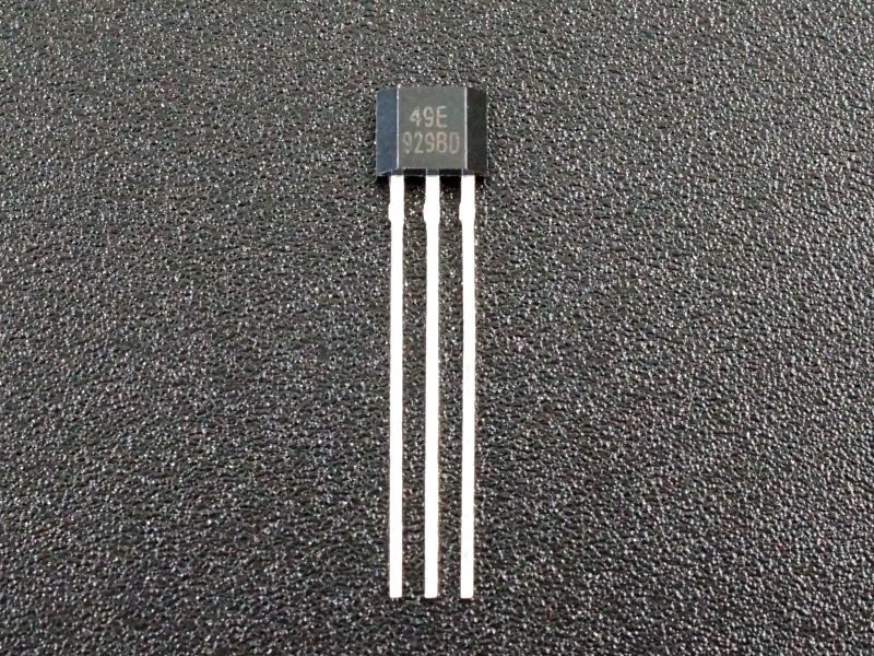
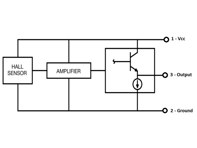
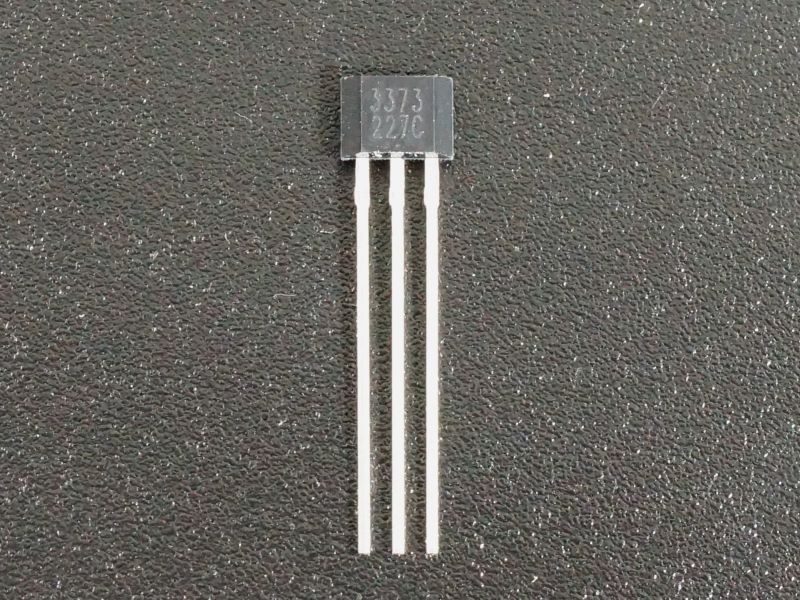
The Hall-Effect Sensor Analog 49E can detect the magnetic N/S pole and relative strength of a magnetic field.
PACKAGE INCLUDES:
- Hall-Effect Sensor Analog 49E
KEY FEATURES OF HALL-EFFECT SENSOR ANALOG 49E:
- Senses relative strength of magnetic field and provides analog voltage output
- Can differentiate between North and South pole of magnet
- 3.3 and 5V compatible
Hall-effect sensors are commonly used for measuring the speed of rotating assemblies where a magnet on the assembly alternately makes and breaks magnetic contact with the sensor as the assembly rotates. They can also be used for applications such as determining when a door has been opened, position sensing and detecting the magnetic field created by current flow in a wire.
The 49E sensor can detect both the North and South pole of a magnet as well as the relative strength of the magnetic field. The side of the sensor with the labeling is the side used for detection.
Hall-effect sensors have several advantages over mechanic switches, chief among them are that by being solid-state, there is no concern about contacts wearing out and the switching speed can be quite high.
The main challenge with using Hall-effect sensors usually resides around the mounting of the sensor and any associated magnets.
Power Supply
The sensor can operate over a Vcc range of 2.3-10V.
If the output is being read by an MCU, it is advisable to operate the sensor at the same voltage as the MCU so that the sensor output will be compatible with the range of the analog input.
The power draw is stated as 4mA nominal but it will vary with Vcc. At 3.3V it draws 5mA and at 5V, it draws 7.8mA. It is possible to power the device off a MCU digital output pin.
Analog Output
The sensor output is an analog voltage. When no magnetic field is detected, the output will rest at approximately 1/2 Vcc. If the south pole of the magnet is brought near, the output will linearly ramp towards Vcc and if the north pole of the magnet is brought near, the output will linearly ramp towards ground.
In the case of Vcc being 5V, with no magnetic field present the output will rest at about 2.5V. If the south pole of the magnet is brought near, the output will raise linearly up to a maximum of about 4.2V. If the north pole is brought near, the output will lower linearly to a minimum of about 1.0V.
The output is typically read by an ADC port on a uC if the strength or pole of the magnetic field is important. Optionally it can be run into a comparator like the LM393 if a digital output with an adjustable set-point is desired. If you are just counting the number of times a magnet goes by, this is easier than working with the analog output. Digital Hall-effect sensors are also available for this purpose.
OUR EVALUATION RESULTS:
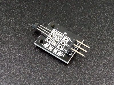
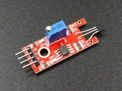
Hall-effect sensors are quite useful in a number of applications and one of the more under utilized electronic components available to hobbyists. These particular sensors are used in many of the analog hall effect sensor modules that come out of China.
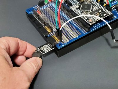
The program below monitors the output of the sensor and reports the value of the analog output. Simply hook the sensor up to 5V / 3.3V and ground and connect the sensor output pin to a analog pin on the MCU. We use pin A0 in this example but this can be any analog input pin.
To calibrate the circuit, run the program with no magnet near the sensor and record the ‘rawValue’ that is being reported. Now change the ‘zeroLevel’ value in the program to the rawValue reading you recorded. This value will be subtracted by the program so that the rawValue reading = 0.0 when no magnetic field is present. Download the updated program and the rawValue reading should now show 0.0.
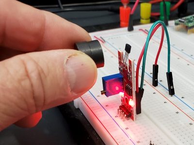
As the south pole of a magnet is brought near, the value should start to increase. If the north pole of a magnet is brought near, the value should decrease (increase in the negative direction).
Hall-effect Sensor Analog 49E Example Program
/*
Analog 49E Hall Effect sensor test

Basic code for reading the analog output of the 49E hall effect sensor.
Sensor is connected to A0, but can be any analog input pin.
*/
const int AnalogPin = A0;
const float GAUSS_PER_STEP = 2.57;  // Sensor outputs approx 1.9mV / Gauss.
                                    // ADC step is about 4.89mV / Step for 5V operation.
float rawValue = 0.0;               // Raw ADC Reading
float gaussValue = 0.0;
float zeroLevel = 518.0;  // Adjust value as needed to get zero rawValue output with no magnetic field.

//===============================================================================
//  Initialization
//===============================================================================
void setup()
{
  pinMode (AnalogPin, INPUT);
  Serial.begin(9600);         // Set comm speed for debug window messages
}

//===============================================================================
//  Main
//===============================================================================
void loop()
{
  rawValue = analogRead (AnalogPin) - zeroLevel;  // Output normalized to '0' with no field present
  Serial.print ("Reading Raw: ");
  Serial.println (rawValue);
  // Reading positive relative to the South Pole, the North Pole negative
  gaussValue = rawValue * GAUSS_PER_STEP;
  Serial.print ("Reading in Gauss: ");
  Serial.println (gaussValue);
  delay (3000);
}
BEFORE THEY ARE SHIPPED, THESE SENSORS ARE:
- Sample tested per incoming shipment
- Packaged in a resealable ESD bag for protection and easy storage.
Notes:
- None
Technical Specifications
| Operating Ratings | Vcc Range | 2.3 – 10V |
| Output | No magnetic field detected | 1/2 Vcc (typ) |
| Magnetic field detected – South pole max gauss | 4.2V (Vcc = 5V) | |
| Magnetic field detected – North pole max gauss | 1.0V (Vcc = 5V) | |
| Sensitivity | 1.9mV/GS (± 0.2mV/GS) | |
| Maximum Gauss | ±1200 GS | |
| Power consumption | Varies with Vcc | 5mA @ 3.3V, 7.8mA @ 5V |
| Package | SIP-3L | |
| Package Type | Plastic, thru-hole | |
| Mfr | China | |
| Datasheet | 49E Hall Effect Sensor |

