GY-906 MLX90614 Non-Contact Precision Thermometer Module
$12.95
High precision infrared non-contact thermometer module with I2C interface and 5V or 3.3V operation.
29 in stock
Description
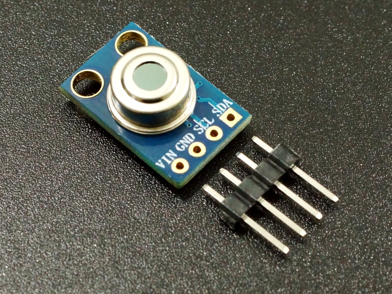
The GY-906 MLX90614 is a high precision infrared non-contact thermometer module with I2C interface and 5V or 3.3V operation.
PACKAGE INCLUDES:
- GY-906 MLX90614 Non-Contact Precision Thermometer Module
- 4-pin male header
KEY FEATURES OF GY-906 MLX90614 NON-CONTACT PRECISION THERMOMETER MODULE:
- Non-contact measurement perfect for measuring temperature of moving objects.
- Temperature measurement range: -70°C to +380°C
- I2C/SMBus interface
- Optional PWM and interrupt output
- 3.3V or 5V operation
The main difference between this and most other thermometers is that the temperature reading is taken without contacting the object whose temperature is being monitored. This can be very useful for monitoring the temperature of something moving like a spinning motor shaft or objects on a moving conveyor built for instance.
Because the sensor is not necessarily exposed to the same temperature that it is measuring, it can read a wide range of temperatures. It has measurement a range of -70°C (-94°F) to +380°C (+720°F) with an accuracy of 0.5°C around room temperature. The sensor itself is rated for -40°C to +125°C.
The sensor has a 90 degree field of view and the reported temperature is the average temperature within that field of view. The appropriate measurement distance therefore depends on how wide of a field of view is desired. If measuring the surface temperature of an an object like an IC or rotating shaft, a measuring distance of about 1 cm is typically used.
The sensor has a built-in optical filter that cuts off the visible and near infrared light to minimize their impact on the reading.
The module has 3 basic modes of operation. It can communicate the temperature or have settings configured using the I2C bus. It can communicate the temperature continuously using a PWM signal where the duty cycle of the signal represents the temperature. It can act as a thermal switch where the output is toggled at a preprogrammed trip point such as when used in a thermostat.
Using I2C / SMBus
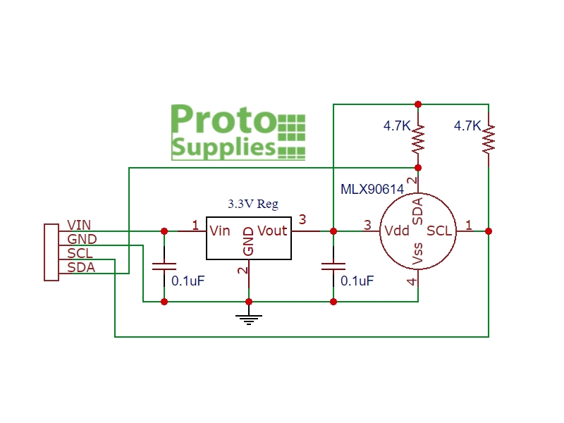
The primary interface to the device is the SMBus which is basically the same as I2C and uses the same SDA (Data) and SCL (Clock) lines. The module has 4.7K pull-up resistors on these lines. The SCL and SDA pins connect to the SCL and SDA pins on the MCU.
The temperature of the object as well as the ambient temperature of MLX90614 can be read in °C and °F. The device uses a high resolution 17-bit ADC and DSP unit which provides a large range, high resolution and very good accuracy.
In addition the device can be programmed over the interface to have one of 127 I2C addresses so that up to 127 of the devices can operate on one I2C bus. A number of other settings can also be configured using the I2C interface such as using the PWM output or thermal switch mode of operation.
Using PWM Mode
When placed into PWM mode, the module outputs a continuous 10-bit PWM signal on the SDA pin which represent the measured object temperature. The module PWM signal by default covers the range of -20C to 120C with an output resolution of 0.14C, but this default range can be adjusted via the I2C bus.
Using Thermal Switch Mode
When using as a thermal switch, a preset temperature can be programmed into the device. When the temperature is reached, the PWM pin is triggered which can be used as an interrupt input to an MCU or can be used to directly drive a relay or similar device. The output drive capability is 25mA.
Supplying Power
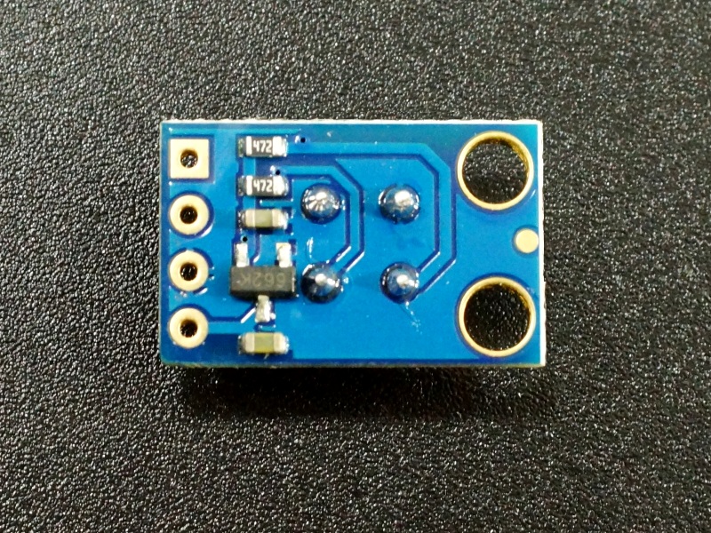
The module has a 662K 3.3V regulator on it. It can handle up to 6V max on the VIN power input pin though 5V is typical. If the module is powered with 3.3V on the VIN pin, the voltage passes through the regulator with minimal voltage drop, so the module is compatible with both 5V and 3.3V MCUs.
Module Connections
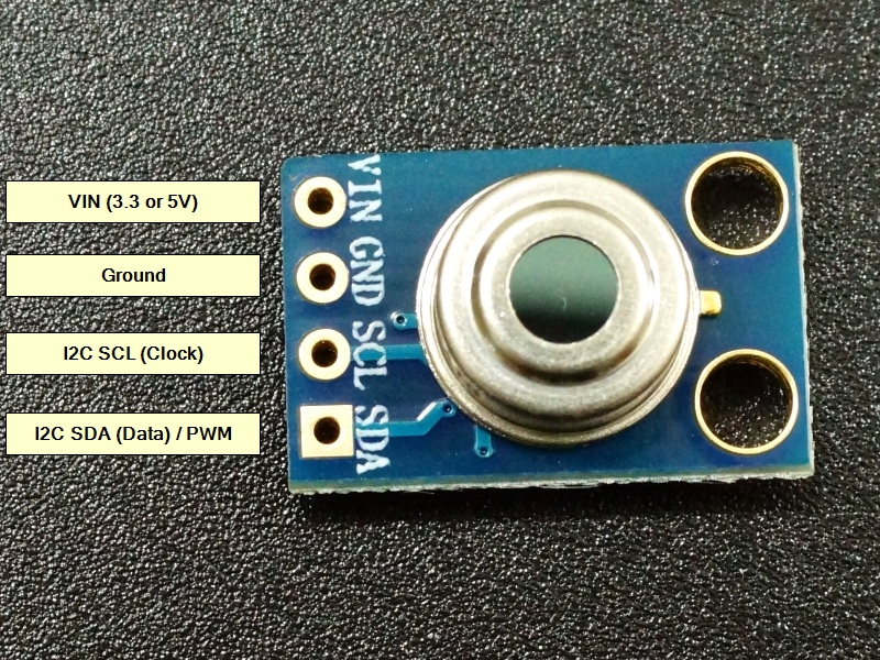
The module brings out the following connections.
1 x 4 Header
- VIN= 3.3 or 5V to match MCU
- GND = Ground
- SCL = I2C Clock
- SDA = I2C Data
Module Assembly
The module ships with the male header strip loose. The header can be soldered to the top or bottom of the module depending on the planned use or wires can be used to make the connections which may be preferable in some cases.
For breadboard use, we put the headers on the bottom. Soldering is easiest if the header is inserted into a solderless breadboard to hold it in position during the soldering process.
OUR EVALUATION RESULTS:
These are nice little assemblies that can be quickly used to do basic temperature measurements. Using the more advanced features definitely require a read of the datasheet.
The program below is a simple test program which prints the temperature data from the sensor to the Serial Monitor Window.
There are several libraries available for the MLX90614 sensor. In the example here, we are using the Adafruit library which is very easy to use, but it just supports basic temperature measurement and not the more advanced features of the device. The library can be downloaded from within the Arduino IDE Library Manager.
To get up and running just connect VIN to 5V or 3.3V to match the MCU and connect GND to ground. Also connect SCL to SCL on MCU and SDA to SDA on MCU.
Download the program and open the Serial Monitor Window to see the results. Ensure the baud rate is set to 9600.
In case you are wondering the Serial.print(“\xC2\xB0”) lines are just there to print the degree ‘°’ symbols.
MLX90614 Test Program
/*
MLX90614 Test Program

Basic program to read the data output of the sensor.
Uses Adafruit MLX90614.h library
Connect sensor to I2C SCL and SDA lines, 5V and ground
*/

#include <Wire.h>
#include <Adafruit_MLX90614.h>

Adafruit_MLX90614 mlx = Adafruit_MLX90614();
//===============================================================================
//  Initialization
//===============================================================================
void setup() {
  Serial.begin(9600);
  mlx.begin();
}
//===============================================================================
//  Main
//===============================================================================
void loop() {
  Serial.print("Ambient = "); Serial.print(mlx.readAmbientTempC()); Serial.print("\xC2\xB0");
  Serial.print("C\tObject = "); Serial.print(mlx.readObjectTempC()); Serial.print("\xC2\xB0");
  Serial.println("C");
  Serial.print("Ambient = "); Serial.print(mlx.readAmbientTempF()); Serial.print("\xC2\xB0");
  Serial.print("F\tObject = "); Serial.print(mlx.readObjectTempF()); Serial.print("\xC2\xB0");
  Serial.println("F");
  Serial.println();
  delay(1000);
}
BEFORE THEY ARE SHIPPED, THESE MODULES ARE:
- Inspected
- Basic operation verified
- Repackaged in high quality resealable ESD bag
Notes:
- None
Technical Specifications
| Operating Ratings | ||
| Vcc Range | 3.3 – 6V | |
| Operating Current | 2mA | |
| Measurement Range | Object temperature | -70 to +380°C (-94 to +720°F) |
| Operating Range | Sensor temperature | -40 to 125°C |
| Measurement | Accuracy over range of 0 to 50°C | ±0.5°C |
| Resolution | ±0.2°C | |
| Distance | 1cm (typical) | |
| Dimensions | L x W (PCB) | 17 x 11mm (0.67 x 0.43″) |
| Country of Origin | China | |
| Datasheet | Melexis | MLX90614 |


