Description
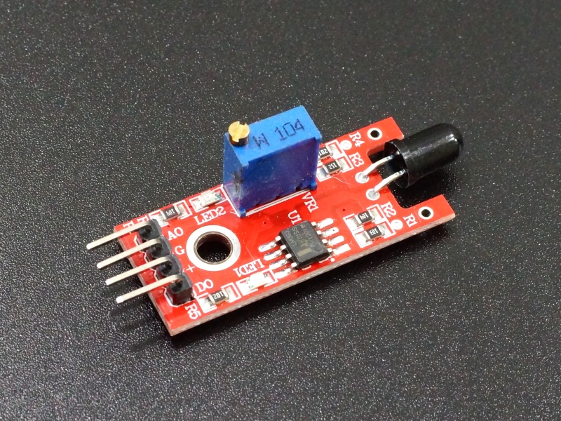
The Flame Sensor Module is used to detect an open flame by detecting light that is in the infrared spectrum as produced by an open flame.
PACKAGE INCLUDES:
- Flame Sensor Module
KEY FEATURES OF FLAME SENSOR MODULE:
- Detects infrared in the spectrum produced by an open flame
- Provides both an analog and digital output with a sensitivity adjustment
- 3.3 and 5V compatible
This sensor module is primarily used to detect an open flame. It does this by detecting light that is in the IR (infrared) spectrum which is emitted by a flame. That spectrum is typically in the range of 700-1100nm.
This module is similar to a regular IR detector, but with a broader detection range. It can be used as a general IR detector for other applications where a broad detection range is desired.
Outputs
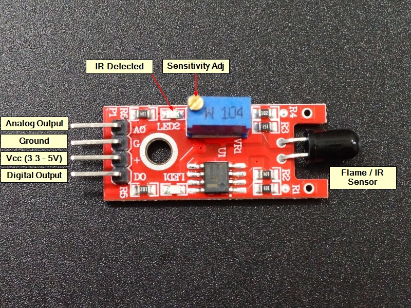
The module has both an analog output and a digital output with sensitivity adjustment on the module.
The Analog output on ‘A0‘ is normally a voltage of approximately 1/2 Vcc when no signal is detected. The actual voltage level will depend on the setting of the sensitivity pot. If a flame is detected, that output voltage will drop towards ground depending on the strength of the IR detected.
The Digital output on ‘D0‘ is normally LOW. When IR is detected by the sensor, the output goes HIGH. The sensitivity adjustment can be used to set the trip point. LED2 will light when the output goes HIGH.
Module Connections
There is a 4-pin header on the assembly.
1 x 4 Header
- GND / G = Ground
- ‘+’ = Vcc (3.3 – 5V)
- A0 = Analog output, connects to analog input on uC
- D0 = Digital output, connects to digital input on uC
OUR EVALUATION RESULTS:
These modules are interesting for experimenting with flame detection as part of a fire detector setup. They can also be used to monitor a flame to determine if it has gone out, such as a pilot light. Commercial fire detection systems often also include light flicker detection to help determine if a flame is present since most sources of IR including sunlight can trigger this module, not just a flame.
The module is straight forward to use. Hook up ground and Vcc (3.3 or 5V). A red LED lights when power is applied. There is a red or green LED2 that lights when IR within the sensor range is being detected. If that LED is always on, adjust the sensitivity adjustment potentiometer CCW until the LED goes off. If a match or other flame is then lit and held in front of the sensor, the LED should come on showing that it is being detected. An IR TV remote can also be used to test the operation of the device by pointing it at the sensor and pressing any button.
The simple program below can be used to monitor both the analog and digital outputs of the device to see how it reacts to the presence of a flame.
Flame Sensor Module Example Program
/*
Flame Sensor Module Test

Basic code to monitor the outputs of the flame sensor module
*/

int flameDigitalPin = 7;  // Random digital pin for monitoring the digital output
int flameAnalogPin = A0;  // Random analog pin for monitoring the analog output
int digitalValue = 0;     // Variable to hold the returned digital value
int analogValue = 0;      // Variable to hold the returned analog value

//===============================================================================
//  Initialization
//===============================================================================
void setup()
{
  pinMode(flameDigitalPin, INPUT);  // Set pin as Input
  pinMode(flameAnalogPin, INPUT);  // Set pin as Input
  Serial.begin (9600);      // Set output window comm rate
}
//===============================================================================
//  Main
//===============================================================================
void loop()
{

    digitalValue = digitalRead (flameDigitalPin);
    analogValue = analogRead (flameAnalogPin);
    Serial.print ("Digital: ");
    Serial.println (digitalValue);
    Serial.print ("Analog: ");
    Serial.println (analogValue);

  delay(1000);
}
BEFORE THEY ARE SHIPPED, THESE MODULES ARE:
- Inspected
- Basic outputs verified
- Packaged in a resealable ESD bag for protection and easy storage.
Notes:
- This module is the same or similar to the KY-026
Technical Specifications
| Maximum Ratings | ||
| Vcc | 3.3 – 5V | |
| IMax | Maximum Current Draw | < 7mA |
| Operating Ratings | ||
| Wavelength | 700-1100nm (typical) | |
| Dimensions | L x W (PCB) | 36 x 15mm (1.4x 0.6″) |


