Dual Display 0-100V / 0-10A Panel Meter
$4.95
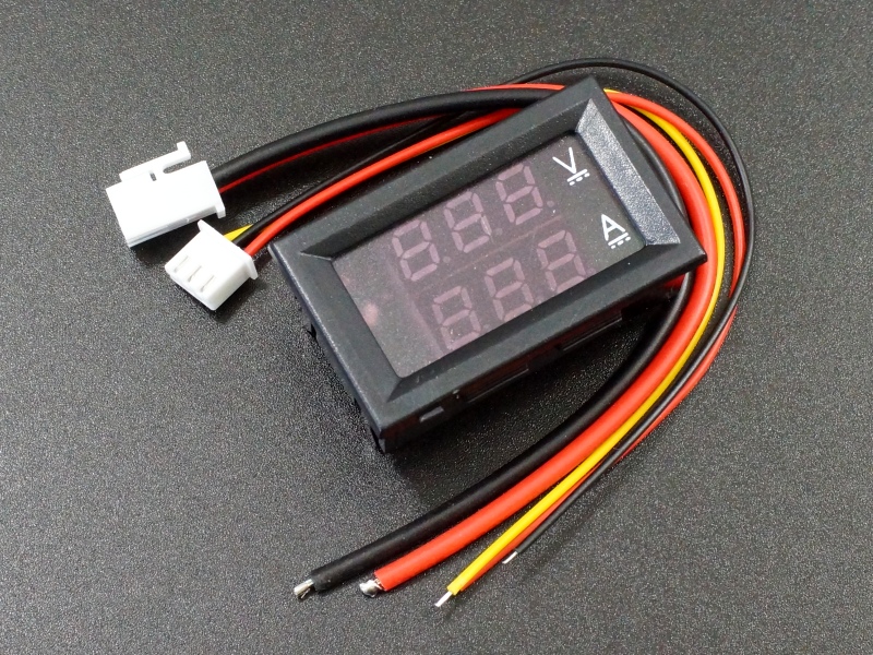
Fully self contained panel meter with dual red and blue display.
13 in stock
Description
This meter is a fully self contained 0-100V and 0-10A panel meter with dual red and blue displays.
PACKAGE INCLUDES:
- Dual Display 0-100V / 0-10A Panel Meter
- Small 3-wire pig-tail connector
- Large 2-wire pig-tail connector
KEY FEATURES OF DUAL DISPLAY 0-100V / 0-10A PANEL METER:
- 0-100V DC voltage measurement range
- 0-10A Low-side DC current measurement range with built-in current shunt
- Dual 0.28″ 7-segment displays
- 4.5 to 30V operating voltage
- ± 1 digit accuracy
These modules work well for monitoring both voltage and current in applications such as solar cells or they can be used in home brew power supplies to provide a digital readout.
Display
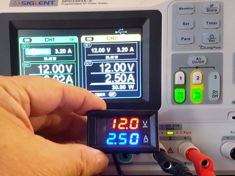
The module has two 3-digit displays each consisting of 0.28″ 7-segment displays. The top voltage display is red and displays the measured voltage and the bottom current display is blue and displays the measured current. Accuracy is ± 1 digit for both displays.
Connections
The meter comes with two wiring harnesses that plug into connectors on the back of the module.
1×3 Wire Harness
The 3-wire small gauge harness is used to supply power to the module and to provide the voltage input for measurement.
- Red Wire = Panel meter power. Connect to 4.5 to 30VDC
- Black Wire = Panel meter ground
- Yellow Wire = Connect to voltage to be monitored
1×2 Wire Harness
The 2-wire large gauge harness is used for measuring current. The meter connects between the negative lead of the load and ground (low side of the load) for measuring current.
- Red Wire = Connects to the negative lead of the load
- Black Wire = Connects to ground
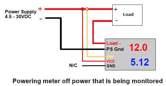
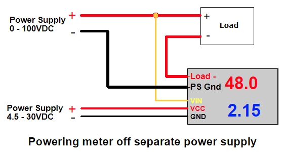
When wiring the module in, there are two basic connection schemes depending on if you want to power the meter from the same power source that you are monitoring or if you are using a separate power supply. Both are outlined below.
Using the same power supply
If the power supply being monitored is 30V or less, the meter can be powered off the supply that is being monitored. In this case, it is not necessary to connect the small black wire since the display ground is internally connected to the same point as the thick black wire.
Using a separate power supply
If monitoring a voltage that can go under 4.5V or over 30V, it is necessary to power the meter from a separate isolated power supply. In this case, the small black wire will need to connect to the ground of that separate power supply.
Voltage Measurement
The yellow wire is the input for the voltage measurement.
Accuracy of the voltage reading is ±1 digit. There is a trimmer pot on the back of the module labeled V or V_ADJ which can be used to calibrate the display against a reference meter if desired.
Current Measurement
The large red and black wires pass the current through a built-in shunt in the module. The shunt may be a wire as shown in the pictures or a large 0.018 ohm SMD resistor. From the voltage drop across the shunt, the meter can calculate the current.
Accuracy of the current reading is ±1 digit. On some boards there is a trimmer pot on the back of the module labeled I_ADJ which can be used to calibrate the display against a reference meter if desired. Other boards do not have this adjustment.
The current can be measured in the positive direction only. If the display is not showing the current reading, ensure that the large black and red wires aren’t hooked up backwards.
Please Note: The meter is designed to connect to the low side of the load between the load and ground. It cannot be connected on the other side of the load between the positive voltage and the load or else the meter will be damaged.
Resetting the Display
We have not seen this happen, but if the meter display gets hosed and the digits are indicating a completely incorrect value, it is possible to reset the meter on some versions of the meter.
To do this, locate the two holes in the corner of the board marked ‘TR’. With power off and no inputs on the voltage and current sense wires, short these two points on the board with something like tweezers and then apply power to the module using the small black and red wires. After a couple of seconds the display will reset and the short can be removed.
Our Evaluation Results:
There are a number of variations of this type of module in the market. The module we sell is the DSN-VC288 module, but there are still two flavors of circuit board. The pictures show both board versions.
We find these modules to be fairly accurate for the type of applications they are typically used in and they hold their accuracy over their measurement range well.
Because the meter current shunt is in series on the ground side of the load, under high current conditions the ground will raise slightly above 0V. This isn’t typically an issue, but something to keep in mind depending on your application.
BEFORE THEY ARE SHIPPED, THESE MODULES ARE:
- Sample inspected and tested per incoming shipment.
Notes:
- None
Technical Specifications
| Display | Voltage | 3-digits Red |
| Current | 3-digits Blue | |
| Character Height | 0.28″ | |
| Measurement Range | DC Voltage | 0 – 100V ± 1 digit |
| DC Current | 0-10A ± 1 digit | |
| Operating Power | Voltage | 4.5-30VDC |
| Current | < 20mA | |
| Dimensions | L x H x D | 48 x 29 x 22mm (1.89 x 1.14 x 0.87″) |
| Mounting hole | 45.5 x 26.5mm (1.8 x 1.04″) | |
| Lead length | 15cm (~6″) | |
| Model Number | DSN-VC288 |


