- You cannot add "USB 2.0 Micro-B Data Cable with Power Switch" to the cart because the product is out of stock.


Teensy 4.1 Fully Loaded
$38.95 – $53.95
Includes 8MB PSRAM & 16MB / 128MB / 256MB Flash or 16MB PSRAM
Select Configuration
Description
The Teensy 4.1 Fully Loaded includes the Teensy 4.1 board with the main pins and Ethernet header preinstalled and optionally loaded with various memory options that can be selected above or down below.
- No Added Memory. Adds the Ethernet header and pins only
- 8MB/64M-bit PSRAM & 16MB/128M-bit Flash
- 8MB/64M-bit PSRAM & 128MB/1G-bit NAND Flash
- 8MB/64M-bit PSRAM & 256MB/2G-bit NAND Flash
- 16MB/128M-bit PSRAM with no Flash
All memory is installed and tested. In additional the selective gold header pins and ethernet connector are added and soldered for a fully plug-and-play board.
Select which version you want and the quantity.
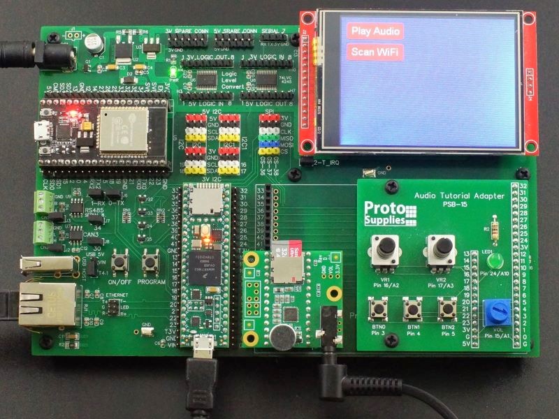
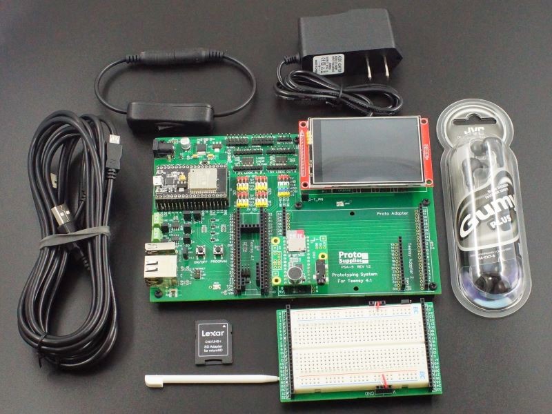
If you are looking for a Teensy 4.1 fully loaded for use with a PCB baseboard that requires the I/O to be brought out from the bottom of the Teensy 4.1 like for use with our Prototyping System or Project System for Teensy 4.1 baseboards, head over to this link: https://protosupplies.com/product/teensy-4-1-fully-loaded-for-prototyping-system/
Please Note: Since this item is hand-modified, we can usually configure and ship additional assemblies within a couple of business days if we have the base Teensy 4.1 and chips in stock. If you have requirements for a larger number than we show in stock or need further customization such as being built using the Lockable version of Teensy 4.1, adding the host USB or VBat header or you want the headers left loose and just install the memory chips, Email us at support@protosupplies.com with your requirements.
Package Includes:
- Teensy 4.1 configured with PSRAM and Flash memory based on selection, header pins and ethernet header installed
- Handy pinout diagram
The Teensy 4.1 has locations for optional 8MB PSRAM (SPI Serial RAM) and Flash (SPI Serial Flash) memory chips that can be installed by the user. These surface mount locations can be difficult to solder and many technical issues are eventually traced back to poor soldering on these components. This is especially true of the WSON Flash memory packages. The Ethernet header can also be a little difficult to install.
For those wanting these parts without the drama, we are offering 5 versions of the fully populated Teensy 4.1 with these chips preinstalled and tested.
DEV-24-B (Bare with No Added Memory) has just the male Ethernet header installed along with standard pins, but no additional memory is installed.
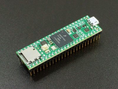
DEV-24 has an 8MB (64M-bit) volatile PSRAM installed along with a 16MB (128M-bit) non-volatile NOR Flash memory as shown below.
The Flash chip will be a Winbond W25Q128JVSIQ. The PSRAM will be one of the following which are all interchangeable: IPUS IPS6404LSQ, ESP PSRAM64H, AP 6404L-3SQR or Lyontek LY68L6400S.
When used with LittleFS file system, the 16MB/128M-bit NOR Flash chip uses the LittleFS_SPIFlash constructor.
#include “LittleFS.h”
LittleFS_QSPIFlash myfs; // NOR FLASH 128Mb
DEV-24-1G has an 8MB (64M-bit) volatile PSRAM installed along with a 128MB (1G-bit) non-volatile NAND Flash memory as shown below for those that need a large amount of non-volatile storage such as for data logging. The NAND Flash is the 8-pad WSON 8x6mm package.
The Flash chip will be a Winbond W25N01GVZEIG. The PSRAM will be one of the following which are all interchangeable: IPUS IPS6404LSQ, ESP PSRAM64H, AP 6404L-3SQR or Lyontek LY68L6400S.
When used with the LittleFS file system, the 128MB/1G-bit NAND Flash chip uses the LittleFS_QPINAND constructor.
#include “LittleFS.h”
LittleFS_QPINAND myfs; // NAND FLASH 1Gb
DEV-24-2G has an 8MB (64M-bit) volatile PSRAM installed along with a 256MB (2G-bit) non-volatile NAND Flash memory as shown below for those that need an even larger amount of non-volatile storage such as for data logging, image files or audio files. The NAND Flash is the 8-pad WSON 8x6mm package.
The Flash chip will be a Winbond W25N02KVZEIR. The PSRAM will be one of the following which are all interchangeable: IPUS IPS6404LSQ, ESP PSRAM64H, AP 6404L-3SQR or Lyontek LY68L6400S.
When used with the LittleFS file system, the 256MB/2G-bit NAND Flash chip uses the LittleFS_QPINAND constructor.
#include “LittleFS.h”
LittleFS_QPINAND myfs; // NAND FLASH 2Gb
DEV-24P has two volatile PSRAM chips installed for a total of 16MB (128M-bit) as shown below. There is no external Flash memory installed as the 2nd PSRAM chip physically occupies the Flash location.
The PSRAM will be one of the following which are all interchangeable: IPUS IPS6404LSQ, ESP PSRAM64H, AP 6404L-3SQR or Lyontek LY68L6400S
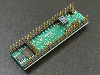
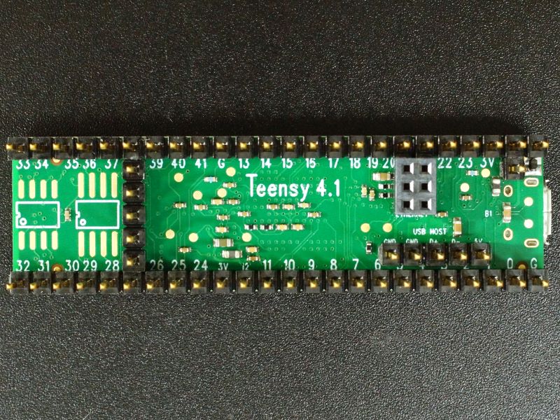
In addition to adding the chips, all the other normal soldering like the selectively plated gold header pins is completed. We also add a gold plated 2×3 2mm Ethernet header for use with the optional Teensy 4.1 Ethernet kit since it is easiest to add it before adding the headers, thus making it fully ready to plug-n-play.
Once assembly is completed, we run test software which is a combination of the PJRC PSRAM and Flash test programs that thoroughly exercises these devices.
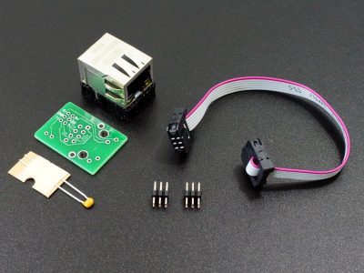
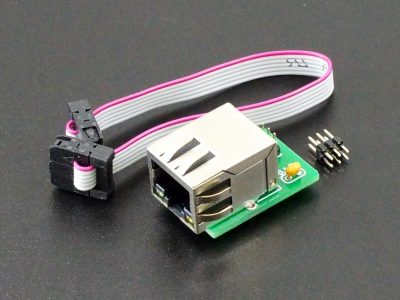
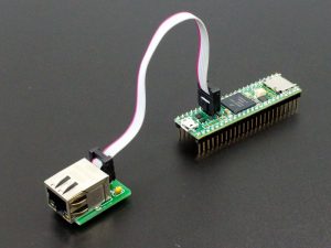
If you are working with ethernet, we also have a fully assembled ethernet port kit available as well.
For more product information click on the picture.
For full details on the Teensy 4.1 as well as additional compatible parts that may be of interest, please refer to the full Teensy 4.1 Product Page.
Before they are shipped, the Teensy 4.1 has:
- 8MB PSRAM chip is installed except for DEV-24-B.
- Either a 16MB, 128MB, 256MB Flash chip or 2nd 8MB PSRAM is installed depending on selection except for DEV-24-B.
- 2×3 2mm gold header for optional Ethernet connection is installed.
- 1×24 (x2) selectively gold-plated male header pins are installed.
- Board is cleaned of flux.
- PSRAM and Flash chip test software is downloaded and run to verify correct chip operation.
- Blink example is downloaded.
- Packaged in resealable ESD bag for safe storage.
FURTHER READING:
LEARN – Working with Teensy 4.1 Memory – Overview of the Teensy 4.1 memory architecture including the optional PSRAM and Flash memories.
Notes:
- None
Technical Specifications
| Microcontroller | NXP iMXRT0162 ARM Cortex-M7 |
| Clock Speed | 600MHz nominal (Optionally 24MHz to 1.008GHz w/ cooling) |
| RAM | 1MB (1024K) |
| FLASH | 8MB (8192K) |
| QSPI PSRAM Chip Location | 8MB PSRAM |
| QSPI Flash Chip Location | 16MB FLASH, 128MB NAND FLASH or 2nd 8MB PSRAM |
| I/O Logic Levels | 3.3V |
| 5V I/O Compatibility | None |
| Output Pin Drive Current | 10mA |
| DC Current that can be drawn from 3.3V Pin | 250mA maximum |
| Operating Voltage | 3.6 – 5.5V on VIN or VUSB pin |
| Typical Operating Current | 100mA typical @ 600MHz |
| Built-in LED | Attached to digital I/O Pin 13 |
| USB Connector Style | Micro-B Female |
| Board Dimensions (PCB) | 61 x 18mm (2.4 x 0.7″) |
| Country of Origin | USA |
| Mfr | PJRC |
| Datasheet | NXP IMXRT1060 |
| Reference Manual | NXP IMXRT1060 Reference Manual |