Pay Additional Charges
Recent Blog Entries
-
Project System for Teensy 4.1 Now Available
We have just introduced our new Project System ... -
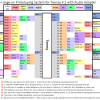
Pin Usage Diagrams Available for Prototyping System for Teensy 4.1
Thanks to the efforts of one of our customers, ...


ESP8266 Witty Cloud ESP-12F WiFi Module
$6.49
Powerful WiFi enabled processor with RGB LED, LDR light sensor and pushbutton.
13 in stock
Description
The ESP8266 Witty Cloud ESP-12F WiFi Module is a powerful WiFi enabled processor in a compact package that incorporates an RGB LED, LDR light sensor and pushbutton for easy stand-alone operation.
PACKAGE INCLUDES:
- ESP8266 Witty Cloud ESP-12F WiFi Module
KEY FEATURES OF ESP8266 WITTY CLOUD ESP-12F WIFI MODULE:
- Microcontroller: ESP-8266 32-bit
- Clock Speed: 80 / 160MHz
- USB Converter: CH340
- USB Connector: Micro USB
- Operating Voltage: 3.3V
- Flash Memory: 4 MB
- Digital I/O: 11
- Analog Inputs: 1
- Communications: Serial, SPI. I2C and 1-Wire via software libraries
- WiFi: Built-in 802.11 b/g/n
- LED: Built-in RGB LED
- Light Sensor: Built-in LDR photoresistor
- Buttons: Built-in pushbutton
- Programming: Compatible with Arduino IDE and NodeMCU
Besides adding WiFi capability, the main claim to fame for the ESP8266 processor over the AVR processor of the standard Arduino is that it has a larger 4 MB of Flash memory and runs at clock speeds of 80 MHz and can sometimes optionally be overclocked to 160 MHz and therefore has a fast processing speed. These can be used as a stand-alone MCU in place of something like an Arduino or it can be used as a peripheral in conjunction with another MCU just to provide WiFi capability.
The module incorporates several common components including an RGB LED and LDR photoresistor which makes it more of a stand-alone device. It also incorporates a pushbutton for initiating an action of some type.
The module is constructed of two stacked boards. The top board is the main processor board with the ESP8266 and the bottom board provides the USB interface. If desired, once the module is programmed and if the USB is no longer required, the top board can be removed and used without the bottom board. Note that the USB connector on the top board can optionally provide power to the module if using it without the bottom board, but it does not provide USB communications.
Digital I/O
All of the Digital I/O support PWM and interrupts except pin 16 which does not support interrupts. In addition they can be configured to have pull-up or pull-down resistors. Though there are 11 digital I/O pins, 2 are typically reserved for use as the TX/RX lines if serial communications are used which leaves 9 digital I/O for other uses. Some of these 9 pins are connected to the on-board LEDs, but can also be used for other purposes if needed.
PWM range by default is 0-1023 rather than the typical 0-255 found on Arduino. The range can be modified using the command analogWriteRange (255) which sets the range between 0-255.
The PWM frequency is 1kHz by default. Similarly it can be modified using the analogWriteFreq(500) to set the frequency to 500 Hz as one example.
The pins are labeled GPIOx. When using with Arduino IDE, the digital pin number is the samethe pin number, so GPIO2 is referenced as just ‘2’.
The small blue on-board LED is connected to pin 2 (GPIO2).
The on-board general purpose pushbutton on the top board is connected to pin 4 (GPIO4).
The RGB LED is common cathode and so lights when driven HIGH. It is connected to the following pins:
- Pin 15 (GPIO15) = RGB Red LED
- Pin 12 (GPIO12) = RGB Green LED
- Pin13 (GPIO13) = RGB Blue LED
Per spec, the digital I/O is limited to 3.3V, but the mfr has made statements that the digital pins are in fact 5V tolerant and there are many installations using the module directly connected to the logic lines of 5V MCUs, so use your own judgment.
Analog I/O
The analog input A0 (ADC) is a single 10-bit ADC input which is connected to the LDR (Light Dependent Resistor).
The LDR has a dark resistance of about 2.5K and is in series with a 470 ohm resistor to form a voltage divider that feeds the ADC input. The LDR is connected to the Vcc side of the voltage divider and the 470 ohm resistor connects to ground. As the light intensity increases, the LDR resistance decreases and therefore the voltage on the ADC input increases.
By measuring the voltage, the relative brightness of the light falling on the sensor can be determined.
Powering the Module
The module can be powered via the USB port on either the top or bottom board or by using an external 5V power supply connected to the Vcc pin.
The top module includes a 3.3V regulator which regulates the 5V down to the 3.3V required by the ESP8266.
Programming the Module
The board uses the CH340 chip on the bottom board for USB communications, so the bottom USB must be used for programming or communicating with the module.
If you have any issues with connecting to the board, you may need to download a driver for the CH340. Just search for Arduino CH340 driver and you will find a number of sources for drivers depending on what Windows or Mac operating system you are using.
The module comes preloaded with the NodeMCU software that accepts the standard AT command set.
It also can be programmed in C using the Arduino IDE and is how the modules are most often used. An example program is shown down below. If a program is download via the IDE, it will overwrite the NodeMCU software or whatever else was loaded before. If that is a problem for what you want to do, the NodeMCU software can always be reloaded.
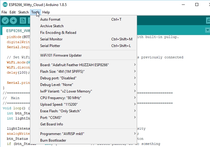
There are many instructions for installing and using ESP8266 based boards with the Arduino IDE, but here is a short-hand version. Note that once the ESP8266 board type is added to the IDE, there will be many more items added to the Tools drop down menu.
- Open Preferences window and enter the following into the ‘Additional Board Manager URLs’ field: “http://arduino.esp8266.com/stable/package_esp8266com_index.json“.
- Under Boards Manager, install ESP8266 by ESP8266 Community.
- Under Tools/Boards select “Adafruit Feather HUZZAH ESP8266“.
- Set Upload Speed to “115200“.
- Select the port that the board is attached to. In my case it happened to be COM3
- In the Serial Monitor window, set comm rate to 115200 and line ending to Both NL & CR
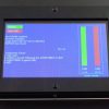
Here is what it looks like on my setup.
To test whether the board is basically working and you can communicate with it using the preloaded NodeMCU software, you can open a Serial Monitor Window and simply enter ‘AT‘ into the serial monitor top window and hit ENTER. The board should return with ‘OK‘. That indicates the board is alive and the setup is working.
If you don’t get the OK:
- Ensure that you have the USB cable plugged into the bottom USB connector, not the top.
- Make sure that you have the correct Comm Port selected.
- Verify the serial monitor window is set to a baud rate of 115200 and the line ending is set to Both NL & CR.
Our Evaluation Results:
These modules have good overall build quality.
Things to Watch Out For
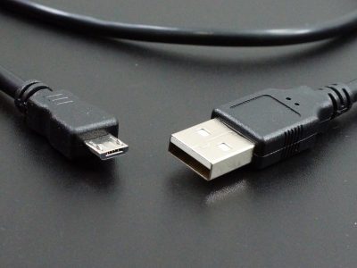
The micro USB connector has a very small footprint and solder pads which makes it popular for small MCUs where space is limited. As with any MCU that uses the micro USB connector, some care should be taken not to put excessive strain on the USB cable or it is possible for the connector to be dislodged from the board.
The Witty Cloud (and ESP8266 processors in general ) have a couple of software quirks to be aware of compared to working with a standard Arduino.
First is that the compile and download time when using the IDE tends to be longer than for typical Arduino boards. This is especially true the first time a program is compiled or if the build options are changed which require a complete recompile. Subsequent compiles do run faster.
The second thing is that the module does not like long delays in code and it may cause the module to do a watchdog software reset. This is because the module has a network stack to handle the WiFi and that needs to be serviced regularly by the processor. An example of what not to do would be using something like a tight DO/WHILE loop waiting for a button to be pressed.
For instance in the example program down below, if you were to check the button using code like this which blocks the program until the button is pushed, you will run into this problem as it does not allow any free time for the processor to go off and reset the watchdog timer on occasion, so it thinks it has locked up and resets itself.
Do {
btn_Status = digitalRead (BUTTON_PIN)
} while (btn_Status == HIGH)
If the module keeps resetting every couple of seconds, look for this blocking type of issue in your code. This can be resolved by inserting the yield() function into the loop as that function lets the processor go off and take care of other business before returning to the loop.
Using the delay() function does not create the same blocking issue because the delay() function internally calls the yield() function every so often.
Example Setup
The program below is based on one of the sample programs ‘WiFiScan’ that is available once the ESP8266 boards are loaded into the IDE. It sends the list of networks found to the Serial Monitor window.
The version here uses the built-in pushbutton to initiate the scan for any available WiFi networks and turns on the on-board LED while a scan is in process. It also monitors the light level on the LDR and adjusts the brightness of the RGB green LED based on the amount of light that the LDR sensor is detecting. If you put your finger on the LDR, the RGB LED should go out.
The only connection that needs to be made is the USB cable to the USB connector on the bottom board. Ensure HUZZAH ESP8266 is selected as the board type in the IDE and the correct COM port is selected. Once the program is downloaded, open the Serial Monitor window and ensure that the baud rate is set to 115200. Once you press the pushbutton on the edge of the top board, a scan of the available WiFi networks will be displayed.
ESP8266 Witty Cloud ESP-12F WiFI Module Example Program
/*
    This sketch demonstrates how to scan for available WiFi networks.
    A button input is used to initiate the scan and the on-board LED
    is lit to indicate when a scan is in process
    On each loop, also check the analog input connected to the LDR and adjust
    the brightness of the RGB Green LED to match the measured brightness.
*/
#include "ESP8266WiFi.h"

const int BUTTON_PIN = 4;    // Define pin the button is connected to
const int ON_BOARD_LED = 2;  // Define pin the on-board LED is connected to
const int RGB_G_PIN = 12;    // RGB Green LED
const int LDR_PIN = A0;      // Define the analog pin the LDR is connected to
//===============================================================================
//  Initialization
//===============================================================================
void setup() {
  pinMode(ON_BOARD_LED, OUTPUT);       // Initialize the LED_BUILTIN pin as an output
  pinMode(BUTTON_PIN, INPUT_PULLUP);  // Initialize button pin with built-in pullup.
  digitalWrite(ON_BOARD_LED, HIGH);    // Ensure LED is off
  Serial.begin(115200);               // Set comm rate to 115200

  // Set WiFi to station mode and disconnect from an AP if it was previously connected
  WiFi.mode(WIFI_STA);
  WiFi.disconnect();
  delay(100);

  Serial.println("Setup done");
}
//===============================================================================
//  Main
//===============================================================================
void loop() {
  int btn_Status = HIGH;
  int lightIntensity;

  lightIntensity = analogRead(LDR_PIN);  // Read the light intensity
  analogWrite( RGB_G_PIN, map(lightIntensity, 40, 1023, 0, 1023));
  btn_Status = digitalRead (BUTTON_PIN);  // Check status of button
  if (btn_Status == LOW) {                // Button pushed, so do something
    Serial.print("Light Intensity Reading: ");
    Serial.println(lightIntensity);
    Serial.println("scan start");
    digitalWrite(ON_BOARD_LED, LOW);       // Turn LED ON
    // WiFi.scanNetworks will return the number of networks found
    int n = WiFi.scanNetworks();
    Serial.println("scan done");
    if (n == 0)
      Serial.println("no networks found");
    else
    {
      Serial.print(n);
      Serial.println(" networks found");
      for (int i = 0; i < n; ++i)
      {
        // Print SSID and RSSI for each network found
        Serial.print(i + 1);
        Serial.print(": ");
        Serial.print(WiFi.SSID(i));
        Serial.print(" (");
        Serial.print(WiFi.RSSI(i));
        Serial.print(")");
        Serial.println((WiFi.encryptionType(i) == ENC_TYPE_NONE) ? " : Unsecure" : " : Encrypted");
        delay(10);
      }
    }
    Serial.println("");
    digitalWrite(ON_BOARD_LED, HIGH);    // Turn LED Off
  }
}
Before they are shipped, these modules are:
- Sample inspected and tested per incoming shipment.
Notes:
- None
Technical Specifications
| Microcontroller | ESP8266 Tensilica 32-bit | |
| Serial to USB Converter | CH340 | |
| Operating Voltage | 3.3V | |
| Input Voltage | 5 | |
| Digital I/O Pins | 11 | |
| PWM I/O Pins (Shared with Digital I/O) | 10 | |
| Analog Input Pins | 1 (10-bit) Max input 3.2V | |
| DC Current per I/O Pin | 12mA (Max) | |
| Hardware Serial Ports | 1 | |
| Flash Memory | 4 MBytes | |
| Instruction RAM | 64 KBytes | |
| Data RAM | 96 KBytes | |
| Clock Speed | 80MHz | |
| Network | IEEE 802.11 b/g/n WiF | |
| Built-in LED | Attached to pin 2 | |
| RGB LED | R = Pin 15, G = Pin 12, B = Pin 13 | |
| General Purpose Pushbutton | Attached to pin 4 | |
| USB Connector Style | Micro-B Female | |
| Board Dimensions (L x W x H) | 32 x 32 x 17 mm (1.3 x 1.3 x 0.7″) | |
| Country of Origin | China | |
| Datasheet | ESP8266EX |
FURTHER READING
Martyn Currey has an excellent series of articles related to using wireless communications, especially with Arduino. This is a link to a series of his articles related to the ESP8266